Daz 3D is part of 
Connect
DAZ Productions, Inc.
7533 S Center View Ct #4664
West Jordan, UT 84084
Licensing Agreement | Terms of Service | Privacy Policy | EULA
© 2026 Daz Productions Inc. All Rights Reserved.
Comments
I've seen sports balls with that 50% squish, so that looks pretty realistic to me,. Cool information, thanks Rich!
thanks Wouldhe and Sapat!
30. Explorations of the Half Sphere
For this section, nothing in particular was planned except to see how the surface parameters from the deflated soccer ball impact a half sphere.
a. First, create a primitive sphere with 10 foot diameter, 64 divisions, and 64 sides. Add a dForce dynamic modifier.
b. Go to the front view for ease of selection. Turn on wire shaded mode.
c. Go to the Tool Settings pane and select the Geometry Editor. Right click in the viewport and choose Selection Mode/Marquee Selection. Hold down the left mouse button and select the bottom half of the sphere.
d. Right click in the viewport and choose Geometry Visibility/Hide Selected Polygon(s).
e. Right click in the viewport and choose Geometry Editing/Delete Hidden Polygon(s). Now you’ll have a half sphere.
f. Run the dForce simulation with the default surface properties. You’ll see the sphere twist into a weird shape.
g. Select the surface and on the Surfaces pane, change Stretch Stiffness to 0.1 and Bend Stiffness to 0.1. Rerun the simulation. Now you’ll see that the sphere does not transform at all but only drops a short distance.
If Stretch and Bend Stiffness are set to 0.2, the sphere will wrap up like in step f. At 0.15 it will look like this. There’s a sharp transition from remaining stable to wrapping up but I don’t know why.
h. Flip the sphere by setting x-rotation to -180. Keep Stretch and Bend Stiffness at 0.1. Run the simulation. In this case, you will see deformation that looks like this:
Compare that to the default setting of Stretch Stiffness 0.8 and Bend Stiffness of 0.5 (below).
i. None of the above simulations had any collisions with other objects. They are just the natural deformation from settling under the default gravity and air resistance settings. If you collide the upside down half sphere with a plane you get this:
Here’s the result of colliding the upright half sphere with a plane. Whereas the upright half sphere without collision showed no transformations, this one clearly does.
j. You can also collide the upright half sphere with a cylinder. In this case it looks a bit like a tablecloth. It required a longer duration (3 instead of 1) to get this degree of draping. i could not get the top smooth - it likely needs more resolutions.
k. I decided to test the half sphere dropping against a figure’s head to see what it would look like. I scaled it down to head size and let it drape onto a G3F. Here’s an iRay render of the “beanie”:
Since the sphere is only a single layer of polygons, the edge has no dimension to it. Using a full sphere and stopping the simulation short can give you a fuller looking beanie.
Here's an updated PDF. It now has 111 pages and covers through section 30. Who knew this would go on so long?
The PDF is too large to attach as is, but if I put it in a zip file I am able to attach it. I'm nearing the limits of what Daz forum accepts, so I likely will split it into two parts with the next update.
EDIT: New version can be found on first post here
Thank You
L'Adair shared in a recent post that not all pillows behave as the ones in Getting a Figure’s Head to Sink into a Pillow. As with other geometries, what works or doesn't work with dForce depends a lot upon how the mesh was made or the scene assembled. Her comment led me to take another look at negative gravity and resulted in this new section (be sure to check out her thread if you haven't, as it has a lot of good information on dForce as well as a way more creative title than this thread).
31. Creating a Round Floor Cushion with Negative Gravity.
Previously I showed how to make a foot stool out of a primitive cube. At the time, I could not get a sphere to deform without it going crazy. With the settings I used in the last two sections, I can now work with primitive spheres. In this section, I’ll discuss two ways to make a floor cushion look like a figure is sitting down into it. Both rely on a weight maps but they are prepared using two different techniques.
a. Create a primitive sphere with 2.5 foot diameter, 64 divisions, and 64 sides. Set the Y-scale to 30%. Add a dForce dynamic modifier and then add a dForce Modifier Weight Node (how to do this is covered in previous sections).
b. Add a figure in a sitting pose. I used Woody for Genesis 3 Males and a Desolation Road sitting pose. Drop the figure to the floor. With the pose I use, the feet are on the ground but the hips leave some space beneath them.
c. Set up an animated timeline. Have the figure above the sphere at frame 0, then drop it down at frame 15. End the simulation at frame 30.
d. Select the sphere’s surface. In the Surfaces pane, set the Simulation Stretch Stiffness and Bend Stiffness to 0.1.
e. On the Simulations Settings pane, set Gravity to -0.5.
f. If you run the simulation as it is now set up, the negative gravity will cause the sphere to go upward and wrap around the figure. It will not look like the figure is sitting on the cushion.
g. One way to keep an object secured from wrapping up and around a figure under negative gravity is to embed the bottom into another object. In this case I used a plane as a floor with the bottom of the sphere below the floor.
It works but the results are not realistic.
h. Select the weight node in the Scene pane and go to the Tool Settings pane and select the Node Weight Map brush. Add the Influence Weight Map. You will see the sphere turn red, meaning 100% influence on all vertices.
i. Use the Side or Front view. Click on the Geometry Selection Mode (the first of the far right icons at the top of the pane).
j. Right click in the viewport and choose Selection Mode/Marquee Selection. Hold down the left mouse button and select the bottom half of the sphere (in the image, it’s the orange area that starts slightly below the midline of the squashed sphere). Right click in the viewport and choose Weight Editing/Fill Selected… and enter a value of 50%.
k. Run the simulation. Notice that we suppressed transformation on the bottom of the cushion, resulting in an abrupt transition from a smooth bottom to a tucked in top.
This looks OK from a higher viewpoint but we can do better.
l. Delete the weight map by right-clicking on the words Influence Weights in the Tool Settings pane and choosing Delete Selected. Click on the Add Map button to re-add the weight map (this is just a quick way to clear out any old settings and start fresh).
m. Use the Side or Front view. Click on the Directional Gradient Mode (the fourth of the far right icons at the top of the pane).
n. This tool will show red and yellow positioning icons in the viewport. Move the red dot (drag on the arrowheads) so it is slightly above the top of the sphere. Move the yellow dot so it is somewhere below. Click on the button Apply Gradient. This will give you a color gradient of red at the top (influence weight 1) to a purple-blue color at the bottom (influence weight less than 50%).
Be sure to click on Apply Gradient any time you change the position of the red and yellow icons.
o. Run the simulation. Now we have a smooth transition without the abrupt change at the midline.
Here’s how it looks from a higher viewpoint.
Thank you for the mention, Rich. And what a great post on using weight maps! (Not to mention, dForce.) I've gotten pretty good at Weight Maps, and I'm embarrassed to say you taught me a number of new things about the Tool options! I've been using Smooth Selected under the popup menu's Weight Editing. (And I've been selecting the Geometry Editor tool at the top of the main window. I didn't even notice the one in the Node Weight Map Brush tool settings.)
This dForce thing is great, but the learning curve, like old age, isn't for sissies! ("Old age" reference is from one of my all time favorite bumper stickers.)
RGcincy: do the 1-foot and 10-foot spheres have the same number of divisions?
Yes they do. I'd be really interested in seeing the equations they use to calculate the dForce effects as that would give a better indicator of why things behave as they do.
Huh. The only thing I can figure is that a smaller surface, by definition, collapses in on itself sooner, and starts colliding with itself sooner.
This is great Rich. I wonder if this would work on something similar to use as a dog bed or cat bed? Only thing is, those have sides, not just an indent.
Good idea sapat! I took what I had and added a center surface and gave it a low influence weight. Added two primitive toruses to be the cording that covers the seam, some leather shaders, and a fox by AM. Looks decent I think. A square bed would be even easier as you already have the side panels built in.
That's really clever Rich, especially using the torus for the cord! Really ingenious. It's amazing what you can do with this.
32. Footsteps in the Snow, Sand or Mud - Part 1
When a person walks along a beach or through the snow or mud, they leave footprints. Most 3D scenes do not show them as they are hard to build into a mesh, especially considering they could go just about anywhere. Here I show how to use dForce to create them in place. This approach uses a primitive plane, the animated timeline, a large setting on the Collision Offset surface property, and a push modifier.
a. Create a primitive plane of size 20 feet and 100 divisions. The more divisions the better to capture the shape of a footprint, but too many slows simulation time.
b. Add a dForce dynamic modifier to the plane. Select the plane’s surface, and in the Surfaces pane, set Simulation/Collision Offset to 6 (default is 0.2). This will keep the plane hovering over the ground when the dForce simulation is completed.
c. Position the plane above a suitable landscape. I used the ground from Forest Winter which has a snowy texture and slightly rolling surface. Be sure the entire plane is above the surface of the ground.
d. Add in a figure with a walking pose. You can use any figure but I used Lorenzo LoRez as it is low-poly and you need multiple copies, then replaced him at the end with a G3M figure.
e. Set the first figure at the end of the path you want to create. Go to the main menu and choose Edit/Duplicate/Duplicate Node Hierarchies. Do this 4 times so you end up with a total of 5 figures. DO NOT CREATE INSTANCES – dForce ignores them during simulation.
f. Position the 5 figures in a line at an appropriate spacing for the pace. Turn off the plane and set each figure at ground level or slightly above. Make a group of the figures for easier manipulation later.
With the plane turned back on:
g. Go to your Timeline pane. Set the counter at Frame 30. Select the group of figures and click on the Create Keyframe icon. Go to Frame 15. Raise the group so all figures are above the plane you positioned in step c. This will also set the group’s Frame 0 height. Be sure there is no timeline movements for the plane – dForce will bring it to the ground. As the simulation runs, the plane will fall first, then at frame 15 the figures will start to fall. This is important as you want the plane to conform to the shape of the ground before the figures push down to create the footprints.
Frame 0: figures and plane above the ground
Frame 15: plane draped on ground, figures still above
Frame 28: figures just making impressions
Frame 30: figures on ground forrming footsteps
h. After the simulation, hide the 2nd through 5th figures, leaving only the first one in line. If you used a low resolution figure for the simulation, you can now load a G3M with a similar walking pose and position it in place of the low resolution figure. Be sure to adjust the legs so the feet match the position of the original figure.
i. For some camera angles, this is sufficient. But if you can see the edge of the plane, it will be hovering above the ground and can cast a shadow or show items poking through.
To correct this, we will add a push modifier and use a weight map to blend the edges of the plane into the ground.
This section continues in next post
Footsteps in the Snow, Sand or Mud - Part 2
j. Select the plane and from the main menu choose Create/New Push Modifier Weight Node…
k. Select the push modifier in the Scene pane, then go to the Tool Settings pane and select the Node Weight Map Brush. Halfway down the tool pane click on Add Map button next to the box that will show <New Push Modifier>. Set the value of the new push modifier to -6 (to compensate for the +6 Collision Offset we used earlier).
l. Go to the top view. Click on the Geometry Selection Mode (the first of the far right icons at the top of the pane). Right click in the viewport and choose Geometry Selection/All. Next choose Weight Editing/Fill Selected… and enter a value of 0%.
m. For the following steps, access the pop up menu by right clicking in the viewport and then selecting the appropriate command.
n. Set Selection Mode to Marquee Selection. Hold down the left mouse button and select the central 75% of the plane. Choose Geometry Selection/Invert Selection so now the outside perimeter is selected.
o. Click on the Paint Brush mode (the second of the far right icons at the top of the pane). Set the sensitivity to 0.6 and paint a red edge along the outside of the plane.
p. Choose Weight Editing/Smooth Selected… and enter a value of 50%. This will smooth your painting from the edge into the middle of the selection.
q. Go to Perspective view and look at the edges of the plane. Use the weight brush to touch up edges so they disappear beneath the surface. You may have to adjust the weight map value from -6 to -6.2 or more.
A spot render showing the plane blended into the ground:
A spot render showing what it would be like without the push modifier:
r. Copy the ground texture to your plane. You may have to adjust tiling and other surface parameters to get it to match. If all is done right, you’ll have a final result that looks something like this.
Areas for improvement:
1. Some of the steps are smaller than the others. I would rotate the figure or change the right leg position on those.
2. The footsteps don’t have enough of a foot shape (more important if bare feet in sand). Start with a higher resolution plane.
Since weight maps can be a bit tricky to paint, I've attached a .duf file with a 100 division plane with the weight map I used to make this scene. [EDIT: I updated 3/19 as the original did not include the dForce modifer. Now when loaded you'll have the plane, dForce modifier, andpush modifier with weight map all ready to go.]
Thats cool!
This. Is. Fantastic!
I've hated to do winter scenes (or sand/mud) where the immediate area of the feet and the apparent path followed show because they never looked real.
Thanks for this!
Thank you! I've been looking for something like this for quite a while
Looks great!
I think I can have it work on animations too...
Brilliant idea! I must try this one out.
This is something I have been thinking about - Spacebones has some obj at Sharecg for different tracks, they work on Booilin (?), which doesn't work in DS, but I've been toying about asking about them in this thread for this very reason - dforce could make use of them...
Glad the footprints look to be of use to so many. Thanks for commenting!
33. More Footprints
Here’s another example of footprints using Nature - Canyon as the setting. This has a ground mesh with even more height variation than the one used in the previous section. The hardest part of creating footsteps using dForce is merging the plane’s edges into the ground mesh and making the surface texture match up with the ground.
a. Repeat the steps from 32 a-g. If you have a copy of the .duf file I posted to the Daz forum, you can skip steps a-b.
b. I created a total of 7 figures in step 32 d-e, as I wanted a longer walk.
c. Because of how the ground bends, I slightly rotated the plane on the X, Y, and Z axis to somewhat follow the tilt of the ground.
d. This is what the figures and plane look like at Frame 0 of the simulation.
e. Run the simulation.
f. If you use the plain downloaded from my post on the Daz forum, you already have a weight map in place. If not, follow steps 32 j-q. I found that to hide the edges, I had to set the value for the push modifier displacement value to -10 instead of the -6 I used in step 32 k.
g. Copy the surface texture from the ground to the plain. For the Nature – Canyon set, the plane is about 1/5 the size of the ground, so I set the Horizontal and Vertical tiles to 0.2. I then changed Horizontal and Vertical Offset to match the edges as much as I could. It helps to use the Aux Viewport to see the changes to the texture as you change the offset. Also for this set, the bump is quite high and can hide the footsteps, so I reduced it by half.
h. Here’s the result of the simulation. You’ll notice something odd: several long ridges starting in the center of the image and extending to the lower right. This is where the plane has bunched up during draping. Many of the rocks you see are part of the ground mesh and there’s a rock hidden underneath the plane in the center and it’s holding the plane up in that location. This bunching make sense when you remember that dForce treats the plane like fabric.
i. You can correct this bunching by changing four of the plane's Simulation surface parameters. Set Stretch Stiffness and Bend Stiffness to 0.01. Set Bucking Stiffness to 0.1% and set Contraction-Expansion Ratio to 101%. This make the plane form fitting and you get the result you see below.
j. This image shows the default bump of the ground in Nature – Canyon. As you can see, the bump competes with the footsteps. They are still visible but not to the extent as seen above. Which you use depends upon your artist eye.
Oh, wow! This is getting good! Love the footprints!
34. Sand Trap. The golfer’s nightmare, landing in the sand trap. The sand is soft and the ball and the golfer sink in – except in Daz Studio. There the sand is stiff and hard, even if the shader gives the look of soft sand. This section uses the Golf Course Bundle: the course itself, the props (club, ball and bag), and the poses for G3M. It also uses the plane with weight map I used in sections 32 and 33.
a. This terrain is a little trickier to add footsteps to, as there’s a sharp division between the fairway’s grass and the sand sloping down into a pit. I also found if I embedded the plane into one edge of the sand trap, it shriveled up and moved away. Not sure why that is, and there may be some surface settings to prevent that, but in the meantime I used an alternate approach.
b. Follow the steps from section 32. For the most part, you do the same setup and simulation.
c. I used the Lorenzo Lorez figures, positioning them from the edge of the sand to the lowest point. I then added in a G3M figure overlapping the last figure (as if you walked down, then turned in place, disturbing the sand in a larger area). The image to the right shows the Frame 0 setup. Note that the plane is above the grass and sand.
d. Run the animated simulation. You’ll end up with something like this. There is no weight map activated yet, so the plane hovers slightly above the grass and sand.
e. The part of the plane above the grass can be hidden by using the Geometry Editor. Use the Lasso selection method to choose polygons and then Geometry Visibility to hide the selection. You can do this in pieces, which is a good idea when you are working near the junction of grass and sand. In the image, the part I hid is shown in red.
f. I started with the same weight map as I did for section 32 with a push modifier displacement value of -10 to merge the sides of the map into the sand. But since I hid the area over the grass, the adjacent part of the plane did not have any weights to smooth it into the sand, so I used the Node Weight Map Brush to add some weight along that edge.
g. I found that I could not fully depress the edge with the brush, and if I set the push modifier displacement value lower than -10, the footprints started to disappear. So I added a SECOND push modifier to the plane, this time with a displacement value of -15. I only had to paint a small amount of the edge with the paint and smoothing brushes. This allowed me to depress the plane enough so a jagged saw tooth edge caused by the hidden square polygons was gone.
h. Hide all the extra figures and render.
With footprints:
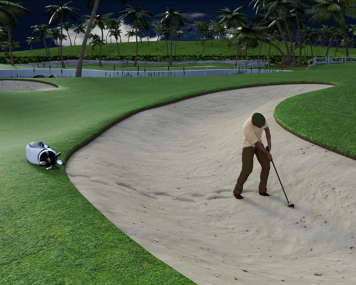
With no footprints: He must have flown or jumped to avoid disturbing the sand!

awesome!
Oh wow! They all look amazing, but the footprints in the sand look so perfectly life-like!
I hope you know how many people you are helping with this thread. I never would have attempted dForce without it, and now I use it all the time! Thank you so much! ^_^