UltraScatterPro Experiments and Experiences
 barbult
Posts: 27,216
barbult
Posts: 27,216
I decided to create a thread to house my UltraScatterPro experiments. I'll try to document what I did and what I learned along the way.
Lessons Learned/Tips:
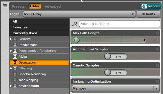
- Before I ever use instances in an Iray scene, the FIRST thing I do is change Render Settings Instancing Optimization from Speed to Memory. You find this setting on the Editor tab in the Render Settings pane. This is documented in the UltraScatterPro manual and is very important. If you leave it on Speed and create a lot of instances, Daz Studio will either become unresponsive or crash.
- When scattered instances will be constrained to small areas of the target surface (by distribution image maps, for example) set the number of instances/iterations much larger than the number that you expect to need, because UltraScatterPro will have to try a lot of positions to find ones in the constrained scatter area.
- Settle on the final morph and pose of the target object before scattering the instances. If the target object is reposed or the shape is changed later, the instances will have to be rescattered.
- If you have the Geometry Editor Tool or the Weight Mapping Tool selected, UltraScatterPro will not generate instances on polylines and polylines will not render.
- The Spacing parameter in the UltraScatterPro Distribution tab will prevent UltraScatterPro from placing instances any closer than this (origin to origin, not edge to edge). It will NOT make UltraScatterPro place them exactly that distance apart. As far as I know, it is not possible to specify and exact distance between instances with a Surface Scatter unless you use a distribution map to control the exact placement of each instance.
- Ground Position Auto in Iray Render Settings ignores instances in computing the "ground" level. This is true for regular Daz Studio instances as well as UltraScatterPro instances.
- UltraScatterPro alignment option "Point At" uses the built-in Daz Studio Point At behavior and it has some unexpected rotation of the XZ plane in some cases. UltraScatterPro has a custom implementation of "Point At with Clamp Y Axis", which behaves consistently without the wonky rotation of the Daz implementation.
- Scattering a group of items creates more variety than scattering just one item, because UltraScatterPro randomly selects one of the items in the group for each instance, instead of using the same one item for every instance. Use the "Create>New Group,,," menu item and then parent your items you want to scatter to the Group. Try this the next time you want to scatter some landscape items. Create a group with a mix of grass, flowers, weeds, etc. and get a more interesting lawn.
- UltraScatterPro lets you import all the settings from a previous scatter into a new scatter. This wasn't possible in the original UltraScatter product and is a huge feature of UltraScatterPro. I used this feature in the Topiary experiement to copy the bottom topiary leaf ball scatter settings to the middle and top leaf balls without having to remember and reenter all the settings.
- A bunch of objects and UltraScatterPro instance groups can be combined into a Daz Studio Group and duplicated. The UltrsScatterPro instance groups in the duplicate remain functional and can still be modified and rescattered! I used the technique to duplicate a topiary tree I created from 4 primitives and 4 UltraScatterPro instance groups.
- If you run UltraScatterPro on an existing scatter group and you change only the Preview instances type (None, Full, Bounding box, Lores tree), you can click on the Cancel button and exit UltraScatterPro. It will keep your new choice of Preview instances without having to rescatter all the instances. This is a huge time saver if you just want to turn off a lot of instance previews in a cluttered viewport, or want to change between Full and Bounding Box, etc.
- You can't scatter instances of instances. If the props you are scattering (like Urban Sprawl 3) contain instances, those instances will not show up in the UltraScatterPro instance groups. They won't cause an error, they just won't be processed.
- All three UltraScatterPro scatter types (Surface, Volume, and Matrix) have an Affinity option for Density Control. Affinity has both Attract and Repel settings. These settings allow you to control how close to and how far from another object's origin your scattered instances will be placed. I think of Attract and Repel kind of like magnetic poles. Attract pulls instances toward the other object and Repel pushes them away from the other object. The Attract settings specify the distance over which instances will be placed, and Repel settings specify a keep-away distance. The Falloff is an ease in/ease out type of control for the boundary of the Attract and Repel range.
- UltraScatterPro version 1.0 "forgets" the target of the Rotation "Point at..." after a scene is closed and reopened. I'm hoping for a future update to fix it.
- Elevation (on the Distribution tab) is measured in Meters. I think everything else in UltraScatterPro is measured in Centimeters. The titles of the numerical entry fields are labeled with the units they use (m or cm), but if you are not observant, and wonder why your elevation values aren't working, it may be that you are thinking in centimeters and not meters.
Post edited by barbult on
Daz 3D is part of 
Connect
DAZ Productions, Inc.
7533 S Center View Ct #4664
West Jordan, UT 84084
Licensing Agreement | Terms of Service | Privacy Policy | EULA
© 2026 Daz Productions Inc. All Rights Reserved.
Comments
Reserved for future use
I am using Daz Studio 4.11.0.236 Public Beta.
Today I decided to play with some of the new freebies. I got Gia 6 Starter Bundle and Teen Josie 6 Starter Bundle. I used Aspen for Gia from the Gia bundle and Scarf Braid Hair from the Josie bundle. I applied Iray shaders to everything that wasn't Iray.
Experiment: Scatter "pearls" in a pattern on a hair band
I only want to scatter pearls on the hair band, not on the hair itself or the cloth in the braid. In fact, I decided I don't even want to show the cloth in the braid, so I turned opacity to 0 on those surfaces. The hair band has some polygons that curl under to give an appearance of thickness. I don't want pearls on the folded under area, so I need to exclude those polygons from the surface to be scattered on. UltraScatterPro can do that by selecting a surface or selection set in the "Limit scatter to" area of the Settings tab and/or with an Image Map in the Density Control section of the Distribution tab. I am going to use both. I will create a selection set to control what polygons will be available to scatter on, and I will use an Image Map to specify a subset of that area to create a zig zag pattern for the scatter.
1) Use the Geometry Editor Tool to create a selection set containing all polygons of the hair band except the ones along the folded edge:
2) Create an image to define a pattern that you want the pearls scattered in
3) Create the "pearl" to be scattered
4) Now you are finally ready to use UltraScatterPro to scatter pearls on your pattern
5) Use UltraScatterPro to scatter smaller pearls in the non-pattern area
Voila!
Lesson Learned: Settle on the final morph and pose of the target object before scattering the instances. If the target object is reposed or the shape is changed later, the instances will have to be rescattered. Rescattering is easy but can take some time for large complex scatters. To rescatter, just select the UltraScatterPro group in the Scene pane and run UltraScatterPro. Then just click the button to perform the scatter.
Original Scatter:
Reposed character head:
Previous scatter groups rescattered:
Excellent idea barbult! looking forward to see what you share
Thanks, Rich. I was inspired by your dForce thread. I wanted a place to document my UltraScatterPro experiments. I thought it would help me remember, give me a place to look back on when I get forgetful ( ) and maybe help others.
I am using Daz Studio 4.11.0.236 Public Beta.
I first posted an overview of this experiment in the UltraScatterPro sneak peek thread.
Experiment: Scatter instances along a polyline framework
I created a low resolution large sphere and converted it to polylines with a Daz sample script. Then I scattered a group of three small colored spheres on the polylines. My scene file is attached, so you may examine it or use it as a starting point for experimentation, instead of starting from scratch.
1) Create the Polylines. You need DS 4.11 or above for this technique. As of today, 4.11 is still Beta software.
2) Create some objects to be scattered along the polylines.
3) Now you are ready to use UltraScatterPro to scatter the small spheres on the polylines
4) Evaluate your results and adjust:
Small spheres scattered on polylines of large sphere:
Small spheres scattered on polylines of large sphere (large sphere hidden to show all instances):
this will be nice to watch!
It is fun to do. I hope you enjoy the adventure.
pulls up chair and gets comfy
I am using Daz Studio 4.11.0.236 Public Beta.
I decided to extend my polylines experiment by modifying some of the polylines parameters and surfaces before scattering instances. I created a cube and generated poly lines with the script. In the Parameters pane, I changed viewport and render line tessellation from 3 to 8. I added subdivision and left view and render subdivision at 1. In the Surfaces pane, I set the Line Start Width (mm) to 250 and the Line End Width (mm) to 5. This made some smooth cone shaped polylines connected at the ends to form a cube.
I scattered a group of 3 gray spheres. I chose 50000 instances and did not set a limit on spacing; I let them overlap. For the rotation I selected Rotation Point = Origin and Alignment = Surface normal. This put all instances around the outside of the polylines.
After rendering, I saw that the Auto ground level of the Render Settings put some of the instances below "ground". Evidently Auto ground doesn't take instances into account???? (This calls for a more detailed experiment to investigate this further.) So, I parented the Cube Polylines oibject to the Cube object and moved the cube up on the Y axis by a value of 20. That brought everything above ground when I rendered again.
Some observations:
The scene file is attached.
Polylines before UltraScatterPro:
Polylines with scattered spheres:
Welcome!
Well, sure enough, further experimentation shows that Ground Position Auto in Iray Render Settings ignores instances in computing the "ground" level. I submitted help request #290270 Iray Ground Position Mode = Auto does not take instances into account.
I created a plane at 0,0,0. then I created a cone and moved it so it was partly below the plane. I created a Daz Studio Node Instance (not even an UltraScatterPro Instance) and moved it even further below the plane. I rendered with Ground Position Auto and Draw Ground On. Auto ground moved the ground level to the bottom of the "real" cone (the lowest "real" object) and ignored the cone instance, which was lower.
This is the viewport view of the scene:
This is what rendered. You can't see the bottom of the cone instance on the right. It is below "ground":
These are great and give wonderful examples of what you can do with UltraScatterPro. Will you be posting the Butterfly House and Mossy Hollow Botanica terrain examples you showed in the UltraScatterPro - sneak peek thread please?
It would probably be hard to recreate my thought process on building those specific scenes. I'll try to do something new with similar techniques, so I can document it as I go along. Thanks for taking an interest!
Experiment: Explore "Default" and "Pont At" Alignment for Surface Scatters
UltraScatterPro has several instance alignment options on the Rotation tab. The default alignment is called "Default". One of the other alignment options is "Point At...". Let's explore Point At alignment and figure out what it is good for. But first we need an idea of what Default alignment does so we can see how Point At differs.
I started with simple primitives to get a feel for what was happening. I created a 4 sided cone and textured it so that each side was a different color. (Texture file is attached if you want to try it.) That way I could tell whether the cone instances were rotated or not. I scattered the cones on a plane. I created a sphere primitive to "point at" later.
This is what I see with Default alignment:
This is what my Default alignment instances look like:
Looking down from the top with an orthographic view, we can see that all instances face the same way on all 3 axes. The point where the Yellow and Turquoise faces meet is the front of the cone. They all face the front of the scene (bottom of the render). (The sphere has no purpose in these renders. It is in the scene for later use with Point At.)
Looking from the front with an orthographic view, we see the same thing; all instances are facing the same way on all 3 axes.
I selected the UltraScatterPro [S] Cone instances group object in the Scene pane and ran UltraScatter again. In the Rotation tab I changed the Alignment from Default to Point At. In the drop down box below Point At, I selected the Sphere as the object for my cone instances to point at. I checked the box for Clamp Y Axis.
This is what I see with Point At and Clamp Y Axis:
This is what my Point At with Clamp Y Axis instances look like:
Looking down from the top with an orthographic view, we can see that all instances are rotated so that their front (point where yellow and turquoise faces meet) now point at the sphere. The instances are still vertical (clamped Y axis).
Looking from the front with an orthographic view, we can see that each instance is rotated in the XZ plane, but they are all still vertical (clamped Y axis).
OK, so what happens if we DON'T check the box for Clamp Y Axis? Well, as you might guess, the instances no longer stay vertical. The instances rotate so that the Y axis points at the Sphere, too. But the rotation in the XZ pane has changed on some of the instances. Is this a bug, or do I not understand how it all works yet? I will try to get an answer. Edit: HowieFarkes as explained what is happening. UltraScatterPro uses the built-in Daz Point At feature, which has the wonky rotation. He wrote his own implementation for the Point At with Clamp Y Axis, which seems to me to work much better.
This is what my Point At without Clamp Y Axis instances look like:
Looking down from the top with an orthographic view, it is pretty hard to visualize what has happened. It is easiest to compare it to the view WITH Clamp Y Axis. Why is the XZ plane rotation different from the version WITH Clamp Y Axis on the instances on the bottom half of the top orthographic view? Edit:See explanation.
Looking from the front with an orthographis view, I see all fronts of cone instances (yellow and turquoise corner). I didn't expect that. I thought it should look like the view with Clamp Y Axis, but with cones tilted toward the sphere. Edit:See explanation.
Experiment Continuation: So what is "Pont At" Alignment good for?
1) Well, let's say you have a character holding a spear and you want a whole bunch of instances of that character pointing at another poor guy. Use a surface scatter with Point At alignment and Clamp Y Axis. Select the poor victim as the object to point at and generate instances of the spear holding character. Here is a simple G3M render of that idea. For simplicity I used assets from Genesis 3 Starter Essentials and my "spear" is just a column primitive. I'm sure you can do much better!
2) Suppose you use some billboard tree instances to populate the background of your scene. But your camera angle is not from the front, or you keep changing your camera angle. Use Point At alignment and Clamp Y Axis with your render camera as the object that Point At points at. Every time you change your camera angle, just rescatter, and all the billboard instances will rotate to face your camera. Here I used tree billboards from Ecomantics - Efficient Ecosystems.
This is what the billboard tree instances looked like from my render camera when scattered with the Default alignment. This won't look good in a scene, because the billboards are viewed from a side angle.
This is what the billboard tree instances look like when scattering with Point At alignment, pointing at my render camera, and Clamp Y Axis. This will look good in a scene.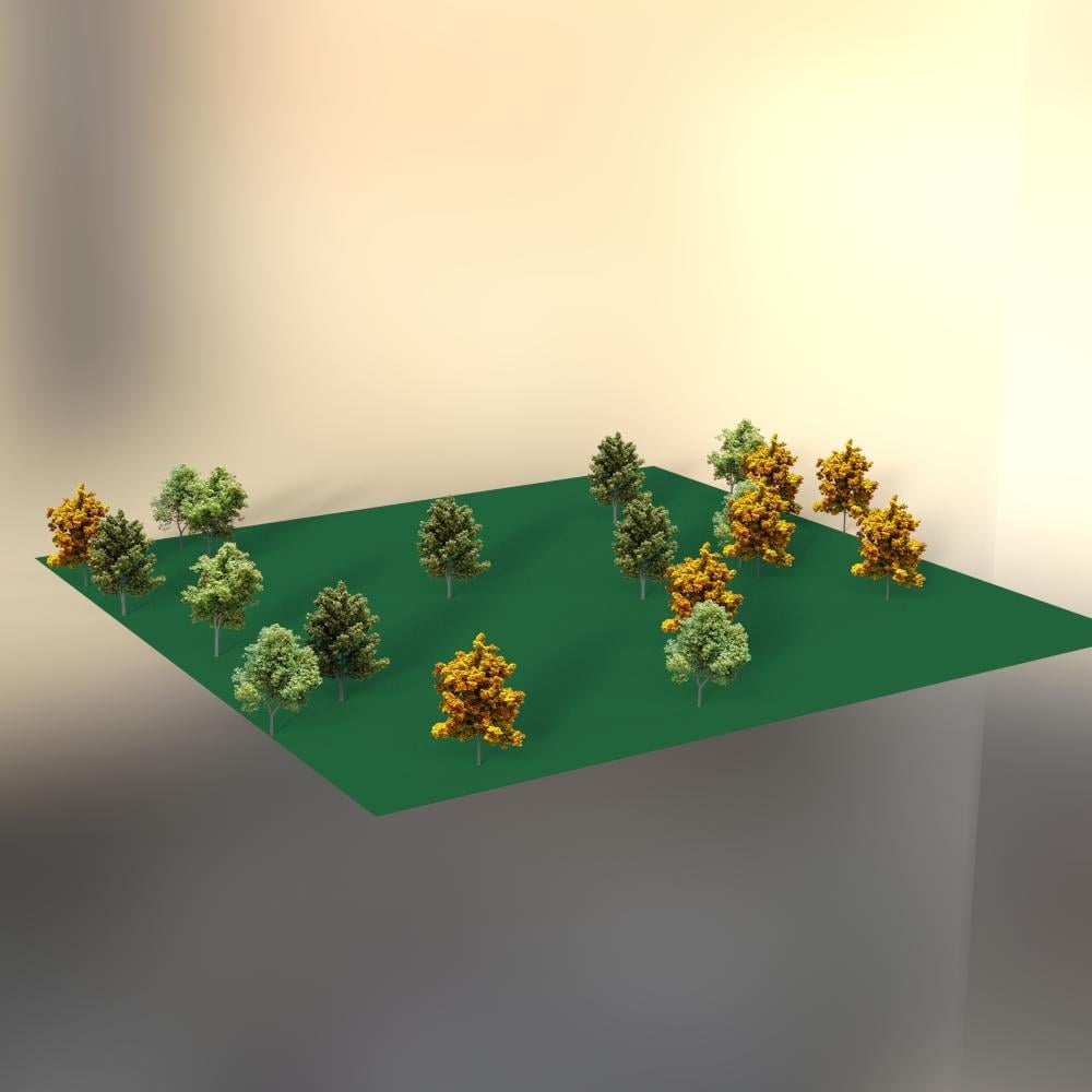
Such a nice thing you are doing, sharing what you're learning with this. Thanks for your efforts, I know from personal experiences how long it takes to document every detail while you're doing it and then write it up. You do an excellent job of covering the steps. KUDOS!
The point at functionality uses Studio's built in "Point At" behaviour. So if you select an object and go to Parameters->General->Point At and select an object to point at - then the same behaviour (complete with weird rotations) is happening with UltraScatterPro too. When you use "Clamp Y" the script actually doesn't use the default behaviour and just determines an angle on the y axis that it can use to rotate the instances.
Also thanks Barbult for creating this thread - you find out things about the script even I don't know or haven't tried.
Great thread - thanks for all of the tips.
@Novica thanks for noticing my thread and your kind words. You certainly know how much effort is involved in a thread like this!
@HowieFarkes thanks for the explanation about Point At. I didn't realize it used a built in Daz feature. Your own implementation with Clamp Y Axis works much more intuitively, I think. Ever consider writing your own Point At and trashing the screwy Daz version? When I get time, I will update my post to include your explanation of the unexpected Point At rotations.
@Artini glad to have you join the thread. I hope to keep adding tips and lessons learned at the top of the thread.
Experiment: Create a Topiary Tree
I want to create fancy topiary trees. I thought I'd start out with a simple one made of a cylinder primitive for the trunk and three sphere primitives for the stacked leaf balls. This will give me a feel for what needs to be done for a fancier tree. I am going to give you the play by play, including what didn't work, and how to fix it. In the end, this is my tree. All of the images are much larger than displaed here. Click them to view a larger size.
Well, you might say that is a lot of work! Do I have to do all that again for each of the other two leaf balls? NO! UltraScatterPro makes it EASY to replicate all this work for the other two leaf balls.
Continued Below
This is going to be a valuable thread barbult. Already showing some cool things with polylines and the topiary tree.
Experiment: Create a Topiary Tree (Continued)
The bottom topiary leaf ball is done. Now we can use a nifty UltraScatterPro feature to quickly build the other two balls. UltraScatterPro allows you to import all the settings of an old scatter into a new scatter.
Experiment: Create a Second Topiary to Make a Pair
What if I want a second topiary to make a pair to flank the front door of my house? Do I have to do all this again?!?!
NO! I am excited to say, that to my surprise, I discovered that I can duplicate the whole tree, instances and all! And even more amazing, they can still be rescattered with UltraScatterPro to make additional changes!
Now that the simple topiary is complete, I moved on to make my fancier topiaries of an elephant and a giraffe. The techniques are the same, I just used ancient Poser props instead of primitives. I even used an UltraScatterPro Volume scatter for leaf trimmings flying off of the chainsaw, but that is a lesson for another day.
The HDRI used in the image is from Aversis.be. It is free for non-commercial personal use.
lol that is awesomeness
@RGcincy @Szark I'm glad you like my topiaries. I particularly enjoyed making the ones with the chainsaw trimming. Have you tried any? I'd like to see what other people come up with.
I haven't as I am weighing up wether to get Pro on what I see here in this thread and so far so good. However I just subscribed to Substance Indie so I will have to wait a little long before upgrading to Scatter Pro. Now if we got an upgrade price I would have gotten it already. :) I will need it eventually though.
yeah I love the chainsaw trimming one, made me chuckle.
Experiment: Create a Parade of People on the Street
Matrix scattering ought to be perfect for creating a group of people who would logically be attired the same and posed the same. Things that come to mind are a choir in robes posed with their hymnals in hand and mouths open singing, or a military parade. I'm going to make a parade of police officers marching down the street. (I'm short on military uniforms, but I have some police.)