Daz 3D is part of 
Connect
DAZ Productions, Inc.
7533 S Center View Ct #4664
West Jordan, UT 84084
Licensing Agreement | Terms of Service | Privacy Policy | EULA
© 2026 Daz Productions Inc. All Rights Reserved.
Comments
Thanks for this thread!
Thanks sberlins
Just wanted to point out a thread showing how to get a dress to drape across a figure and a horse. It cleverly uses animation of a horse/figure that starts upside down and then flips into place. It illustrates that with dForce you sometimes have to be creative in how you set it up to get the results you want.
22. Banner Flag
Flags are a natural for dForce. Since there’s a test scene of conventional flags in dForce Starter Essentials (which comes with Daz Studio 4.10), I decided to test a longer banner flag that is found in FirstBastion’s Ridge Walk Mountains. That flag is already configured by the PA to look like it’s blowing in the wind but you can also transform it with dForce. After running a few tests with his flag, I replaced it with a primitive plane of similar size to see how that looks. Here are the results.
a. This is what the flag prop looks like. It has the flag, a pole, and a set of rocks.
b. Select the flag prop and from the main menu select Edit/Object/ Geometry/Add dForce Modifier: Dynamic Surface.
c. Run the dForce simulation. What you will see is the whole prop begins to sag:
d. Since the pole and rocks have separate surfaces, you can quickly turn them off by going to the Surfaces pane and set Visible in Simulation to off.
e. Now you’ll find that the flag slips down the pole. To correct, you need to add a weight map to keep the portion wrapped around the pole in place.
f. Add a weight map as normal by having the flag prop selected then go to the main menu and choosing Create/New dForce Modifier Weight Node. Select the new node in the Scene pane, go to the Tool Settings pane and select Node Weight Map Brush, then click the Add Map button. Using the brush and holding down the Alt key, remove color from the area around the pole as shown below (area in gray).
g. Now when you run the simulation, the flag stays at the top of the pole while the flaps hang down.
h. Add a wind node and set it to blow at an angle to the flag (since the prop was built to have the look of wind blowing, blowing it in a different direction lets you see the effect wind is having). I set Wind Speed to 5 mph which will make the flag stream horizontally.
Side View:
Top View at Start:
Top View midway:
Top View at end:
The flag after the simulation is complete:
i. Next I added a primitive pane with 50 divisions and sized and positioned it to match the previous banner.
j. The primitive plane won’t wrap around the pole, so I kept that part of the original banner. To do this, select the flag prop, go to the Tool Settings pane and select the Geometry Editor, then using the tool, select all the polygons of the flag that project from the pole and assign them to a new surface. Next go to the Surfaces pane and set that surface to an opacity of 0 and it will be hidden from view.
k. Here is the new flag at 3 wind speeds.
0.1 mph:
5 mph:
10 mph. At this higher speed, the end of the flag gets compressed into a tiny strand:
l. Depending upon the look you desire, there are some surface parameters you can change. These all use the higher wind speed of 10 mph.
1.0 (default):
0.88:
0.8 (default)
0.9
0.98
1.0
m. Mesh resolution has a big effect, but this is harder to achieve as you have to make a new plane (I tested using sub-D on a low resolution mesh but it wrapped the same as the original low mesh).
50 by 50 mesh (used in images above):
20 by 20 mesh:
10 by 10 mesh:
Thank you for this section on the banner. Much appreciated for content and your attention to detail.
I don't think I understand. I've tried to follow this yet can't seem to replicate the results. I tried a simple scene with a plane and a sphere yet struggled to get the plane to conform to the sphere correctly.
First, I converted the plane to subd and gave it a few subdivisions. I forgot how to make it keep its square shape, but whatever.
https://drive.google.com/open?id=1jdzFSyZLOLJzjAJAY1XbrhOO3L06lnjQ (Not sure how to properly post images on here)
then, I opened the simulation pane and simulated it with the default settings, causing this
https://drive.google.com/open?id=1i8LFEobvyBkK15ZCG7Rgdz1gJhoUqTdD
I tried fiddling with different settings and tried placing the plane under the sphere but they ultimately lead to similar flops.
What exactly am I doing wrong?
How many divisions did you give the plane when you created it? It needs those, not the virtual divisions from SubD. (Keeping corners and edges in SubD is controlled by the Edge Interpolation setting under Mesh Resolution in the Parameters pane.)
Yes, RGcincy told us that a primitive plane might need upwards of 50-100 divisions when you create it. I had a problem with a plane reacting properly and that's what he told me to do.
What's the resolution (how many polygons) on your plane? You probably need something like 50 or more so there are places for the mesh to bend. It looks like there's a lot of polygons but if they are from sub-D that won't help
Any advice on dynamic settings for chainmail? It's heavy, but made of a lot of joints.
My sense is that chainmail if fairly flexible because of all the joints but it's weight would make it resistant to wind and slower to change position when moving about.. I would also think weight would also cause draping to be relatively vertical. A high air resistance might help. Have you tried a render? If so, post it and say what doesn't look right about the draping.
I ran a test on a chainmail shirt (from Knight Guard for G2M). It draped fine but I only used the default dForce values. No weight map either. Here's the result:
I'm using the Voyager for M6 tunic that I've retextured as chainmail. When I try to dforce, it goes sideways instead of down.
This is without dForce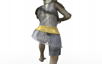
And this is dForce with a weight map locking tight everything bust-up.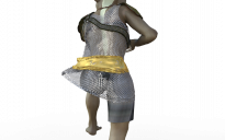
Err, I'm not sure how to look that up or change that. But I did try this on an actual blanket model with its own set of polygons and it did the same thing. It kinda falls down a bit into the shape of a Pringle's chip as if it acts like the model underneath doesn't exist.
That's odd. Not sure what's going on. If those are primitive models, you could post a scene.duf file and I could take a look.
You can find the number of polygons by selecting the object, going to the Tool Settings pane and select Geometry Editor. You'll see a category called Face Groups and a column called Total. Total is the number of polys for each Face Group (there may be only one or there may be dozens depending upon how the mesh was made).
I have that item so I took a look. After suffering through a half dozen system crashes, I finally got it to simulate by turning off Visible in Simulation for everything except the tunic, setting Self Collide to off for the tunic, and hiding the big belt polygons in the Geometry Editor (not sure that's needed). I used default dForce surface parameters, gravity, and air resistance. I set the dForce simulation to animated using the timeline and went from a zero pose at frame 0 to the shown pose in frame 15. I also added a chainmail shader (different than yours).
Here's the weight map:
After the simulation render. A little tight across the back with some indications of mesh stretching:
After turning the belt back on. It's a little loose in this view; from the other side, it has chainmail poke through.
No unusual lifting. I had all the zbrush and adjust fit morphs turned off. You don't by chance have one of those on?
I had some fit control morphs dialed in. It looks like turning off self-collide was the big thing - I've got it working now. The belt's giving me a bit of trouble because I want to drape it a bit differently than the rest, so I'll probably just hide it and put a different belt on.
Well, here's the scene
https://drive.google.com/open?id=1PECtz85yo-cl_pvksKfJKSMWZ7Ec2o_4
and here's the screenshot
https://drive.google.com/open?id=1jlgJyAcltpK_P6W2j9jONG_Y3a69J8nk
I didn't see "total", only "count", and the number was 1
The means it has only 1 polygon. That won't drape as there needs to be multiple polygons.
I notice you used the default cubes in a tutorial; I found those helpful and interesting btw, thank you.
I sub-divided a cube in Blender, did a basic unwrap and added to Studio - available on my deviant art page: http://fav.me/dbz5kwj
Did you have the belt's collision layer set 1 higher than the shirt? I've found that really helps. Also Collision Offset. I've had to go as high as 0.6 on some items.
Hmm. Not sure how to "increase" polygons beyond subd, as I didn't see it being done in the tutorial.
But I also had that same chip-shaped, object-ignoring problem with an actual bed cover prop with multiple polygons. I tried yet another bed like this
https://drive.google.com/open?id=1ivNEoYJPD7WXaRuA5hqfTp5cWfUvK37H
but it resulted in this mess
https://drive.google.com/open?id=1xWEG_OJ0kZJW_pK1LkM_DNzr68csVxOk
You can only increase the number by taking the object into a modeling program where you can add more polygons. If you are following what I wrote, a square primitive plane with about 50 divisions will work (I have not had success with circular meshes I have available).
The bed prop has an irregular polygon pattern with a lot of triangular polygons. My limited experience with them show they can be harder to drape as you are finding. In terms of the pictures you linked to, those long triangular strands come from where the bed cover mesh is touching another object. Those places of touch act to secure the meshes together and you'll see this elongated stretching if the rest of the mesh rolls up or explodes. Since the mesh is bunching up, I'd suggest that in the surface pane you (1) turn Self Collide to off (2) reduce Dynamic Strength to something between 0.8 and 0.9 and see if that helps.
No I didn't. I tried your suggestion and the belt still had lots of poke through and mangling. Just for learning sake, I tried some more things and got it to work:
1. The belt on the tunic has separate polygons but they sit right on top of the underlying tunic material so they get frozen to it and take on it's draping.
2. To eliminate that, I used two copies of the tunic (not instances). Tunic 1 had the belt polygons selected in the Geometry Editor then:
Tunic 2 was similar except choose Hide Unselected Polygon(s) in 2nd step.
3. Tunic 1 used the weight map I showed in a previous post. Tunic 2 had a weight map that was filled to a constant 0.4.
4. Tunic 2 was assigned Collision Layer 2 and Collision Offset of 0.5 in the surfaces parameters.
5. Tunic 2 was parented to the figured (not fitted). It was also moved up the Y-axis off the hips so the polygons didn't touch.
6. On the animation timeline, the belt moved down to the hips as it proceeded.
Here's the front view and you can see the belt has no poke through and looks smooth across the hips and waist.
Here's the back view.
Note polygon stretching is causing stretching in the chainmail texture just above the belt (you see similar stretching on the lower hem). That probably means the belt touched a little early and locked the polys together, so some fine tuning could be done. The angle between the legs is fairly extreme compared to normal posing, so that puts more strain on the fabric and the simulation
I've started to take a more detailed look at the scenes Daz provided in dForce Starter Essentials to further my understanding of dForce behavior. Here is the first one I've looked at.
23. Effect of Surface Properties Using Simple Sheet Drop - Part 1. The simple sheet drop is a scene in the dForce Starter Essentials, which comes with Daz Studio 4.10. The sheet has a number of simulation surface parameters that are different than the dForce defaults. In this section, I’ll compare the original scene settings to the default surface properties, then show what happens when you change an original setting back to the defaults one by one. The only changes to the scene I made was to move the sheet so it doesn’t cover the figure’s head and use different shaders. It's easiest to see differences if you click on the images which will open them in a new tab and you can flip through them.
a. Original scene settings and figure’s pose. With the knee up, there’s more room for draping than what I had in my original blanket tests.
b. Original scene settings (left or top, depending upon how your browser displays them) vs. dForce defaults (right or bottom). The scene settings result in a less stiff draping that more closely hugs the figure and bed. The fabric is more rounded over the knees and foot and there is more dipping between high points. The defaults might be better for a stiffer blanket while the scene settings would be better for a sheet.
c. One by one replacements. Because the scene settings result in a drape much different from the original, keeping 5 of the 6 scene settings lets you see how one set back to default is affecting the drape. For each parameter change, I show an image of the resulting sheet (blue) plus a second image with the original sheet (yellow) also visible. Whichever color is visible indicates a higher elevation.
d. Stretch Stiffness at default (0.8 vs. original scene at 0.01)
e. Shear Stiffness at default (0.2 vs. original scene at 0.01)
f. Bend Stiffness at default (0.5 vs. original scene at 0.01)
g. Buckling Stiffness at default (5% vs. original scene at 2%). The intermingled colors on the overlay image shows buckling stiffness had little effect.
h. Buckling Ratio at default (70% vs. original scene at 98%)
i. Density at default (180 vs. original scene at 80)
j. Conclusions. It’s easiest to see differences if you open each image in a separate browser window. You can then flip through them to see what is happening.
Interesting results. Lots of odd little ripples in most every one though. Any cure for that?
I don't know. Depending upon where the ripples are, lower friction on the sheet or the bed/floor might help (but too low and things can slide right off). Also, I didn't resize the sheet when I moved if off the head, so more is on the floor at the foot of the bed (the sheet lying on the floor at the sides of the bed was in the original scene). Making the sheet fit so it doesn't hit the floor might help.
Yes, maybe it's as simple as resizing the sheet. I'm not well enough to concentrate on this or I'd give it a go. Need to wait til I'm better.
Sorry to hear you are ill. Hope you feel better soon.
Thanks so much :)
Just thought I'd add that dForce can be used on some jewelry items like farah bangles to make them slide naturally up and down arms.
Scott