Cel shading / toon shading in 3Delight and Iray
 KFR6
Posts: 21
KFR6
Posts: 21
Update: the shaders in this thread were made with Daz Studio 4.15.0.30.
After having done some groundwork on outlines and edges, it was time to experiment with shading. Here are my results.
General principle
The main idea that I will apply in both 3Delight and Iray is to try to use the diffuse lighting to create a gradient between two colors, namely a Dark Color (low light) and a Light Color (intense light).
3Delight makes it easy by having a [Color] output pin on its Lighting/Diffuse/Diffuse brick. By using this brick with a default white color, the output can be used as a driver for a user-defined gradient, resulting in full control over colors of the lit and unlit areas.
In Iray, it's more complicated. To my knowledge, there is no way to extract the computed diffuse lighting from a material brick in an Iray shader. So I tried experimenting with two options:
1. Figure out a way to use the Iray lighting to get the result. Although many stars have to be aligned to get the effect right, the keys are a custom normal map (to get the sharp transitions), and splitting the Dark and Light colors between emission (Dark Color) and diffuse tint (difference Light Color - Dark Color). Iray Uber Base works here, no custom shader.
2. Implement partially a Phong model in MDL to do a diffuse mix like in 3Delight, and let the user decide how to split the computed color between emission and diffuse.
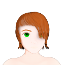
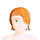
Here is a comparison of the 3 methods (3Delight custom shader, Iray Uber Base, Iray custom shader):
| Soft transitions | Sharp transitions | |
|---|---|---|
|
3Delight All-in-one custom shader |
 |
 |
|
Iray Skin + Hair: Iray Uber Base Outline: Inverted Hull geoshell |
 |
 |
|
Iray All-in-one custom shader |
 |
 |
I will split the text in 2 parts. The first part is about 3Delight, and the second part about Iray will be posted shortly.
Part 1 of 2: Cel shading with 3Delight
1.1. The shader
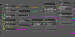
Here is the shader that I will be describing:
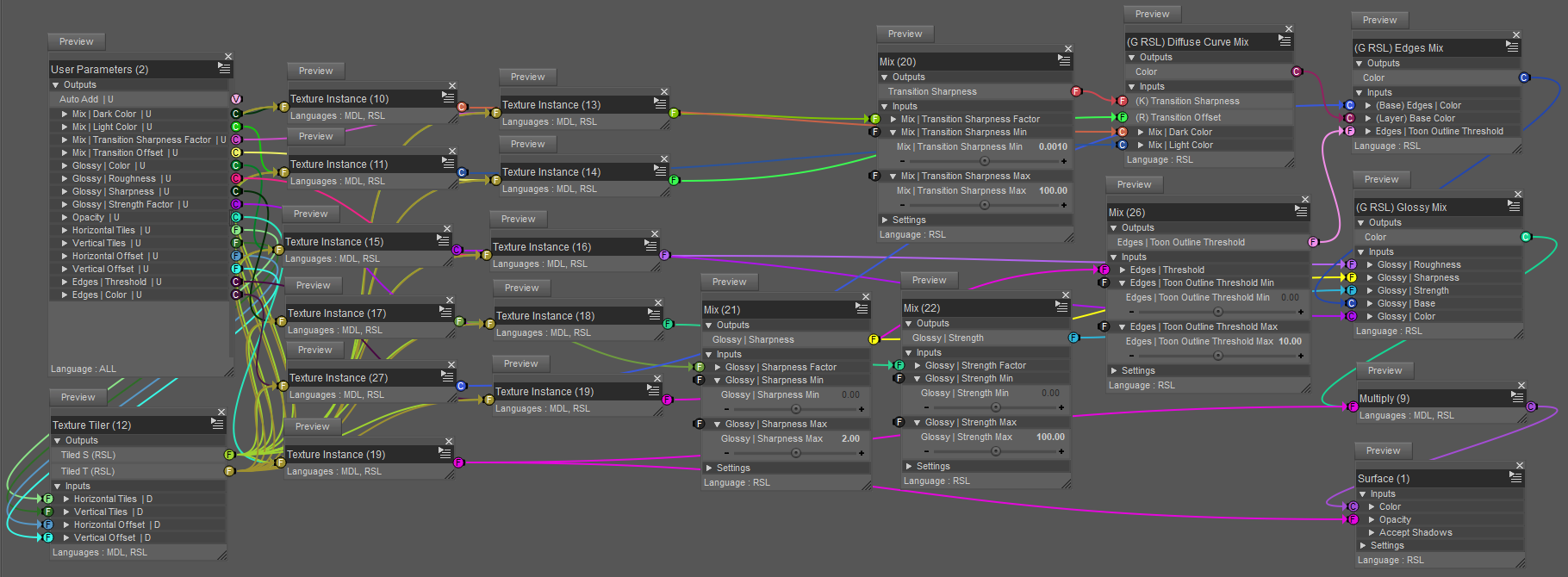
The visible bricks can be broadly categorized in two groups:
- the inputs: Utility/User Parameters, Textures/Texture Instance, Mathematical/Mix;
- the processing pipeline and output: (G RSL) Diffuse Curve Mix, (G RSL) Edges Mix, (G RSL) Glossy Mix, Mathematical/Operators/Multiply, Surface.
Regarding the inputs:
- many parameters are mapped, ie you can use a texture to define the value. That is what all these Textures/Texture Instance bricks are for. They make the shader look more confusing than it needs to be, but this feature is very useful to add regional sub-gradients on a model, like skin details.
- In this shader, mapped parameters are limited to be between 0 and 1 (I don't know if it is possible to go beyond, but this is what I use) so sometimes they have to be transformed before being used. This is what the 4 Mathematical/Mix bricks do.
Regarding the processing pipeline:
- the custom brick (G RSL) Diffuse Curve Mix computes the diffuse lighting;
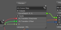
- this computed diffuse factor is then sent to a custom (G) Curve Step brick which is used to change the sharpness of the gradient;
- the output of the (G) Curve Step brick is then used to compute the gradient between Dark Color and Light Color;
- an edge detection is then added by the custom brick (G RSL) Edges Mix;
- the resulting color, combining diffuse mix + edges, is then mixed with a glossy layer;
- finally, the combined [diffuse mix + edges + glossiness] color is multiplied by the opacity and sent to the output.
I will now describe the 3 main pipeline bricks, the most important being the first one.
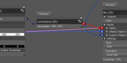
(G RSL) Diffuse Curve Mix
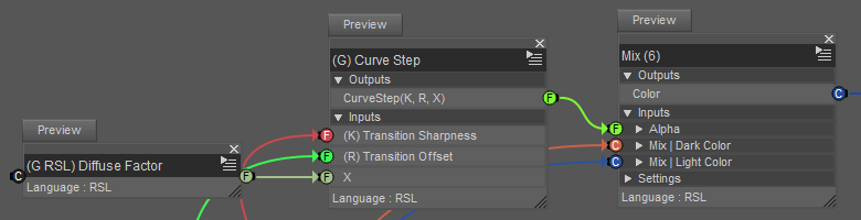
The custom (G RSL) Diffuse Factor brick outputs the lighting information as a value between 0 and 1. This value is modified by a custom sharpening/softening brick (G) Curve Step, and the result is used to compute the gradient between Dark Color and Light Color with a Mathematical/Mix.
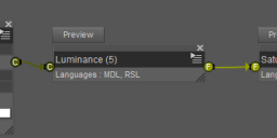
(G RSL) Diffuse Factor
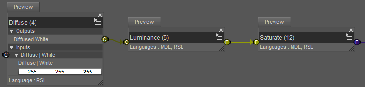
Pretty straightforward:
- Lighting/Diffuse/Diffuse has its input color set to white;
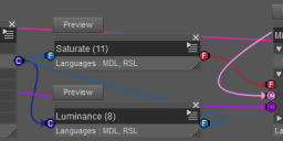
- The result is converted to grayscale with Mathematical/Standard Functions/Luminance (I think it is the MDL function luminance, which computes 0.212671 · R + 0.715160 · G + 0.072169 · B according to the MDL specification 1.7.1);
- Mathematical/Standard Functions/Saturate clamps the result between 0 and 1.
(G RSL) Curve Step
This is the implementation of the function that changes the sharpness of the gradient. It is essentially a customizable smooth step function.
I will first explain the theory, and then I will show the brick network.
a) The theory
A common way to achieve a curve sharpening effect would be to start with a s-shaped curve, and by scaling its argument the "s" could be re-shaped into a diagonal line or a sharp step.
I initially wanted to use the trigonometric function atan for this, because it is naturally s-shaped and I would only have to adjust the center (offset) and the bounds (map to range [0,1]).
However, the brick Mathematical/Standard Functions/Atan doesn't seem able to take arguments greater than about 4 or 5, after which the output looks random.
I didn't try to do a sigmoid using exp because I thought that if 3Delight can't do atan, then perhaps it won't do exp either.
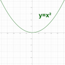
I knew however that Mathematical/Standard Functions/Pow worked, because I had used that brick in other shaders. So I decided to build a parametric function from scratch by stitching together pieces of power functions.
Here is an illustration of the process:
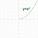
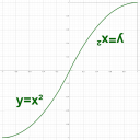
| Step 1: start with a power curve that behaves nicely between 0 and 1 |  |
|---|---|
| Step 2: isolate the part between 0 and 1 |  |
| Step 3: duplicate, move and rotate to get a s-curve | 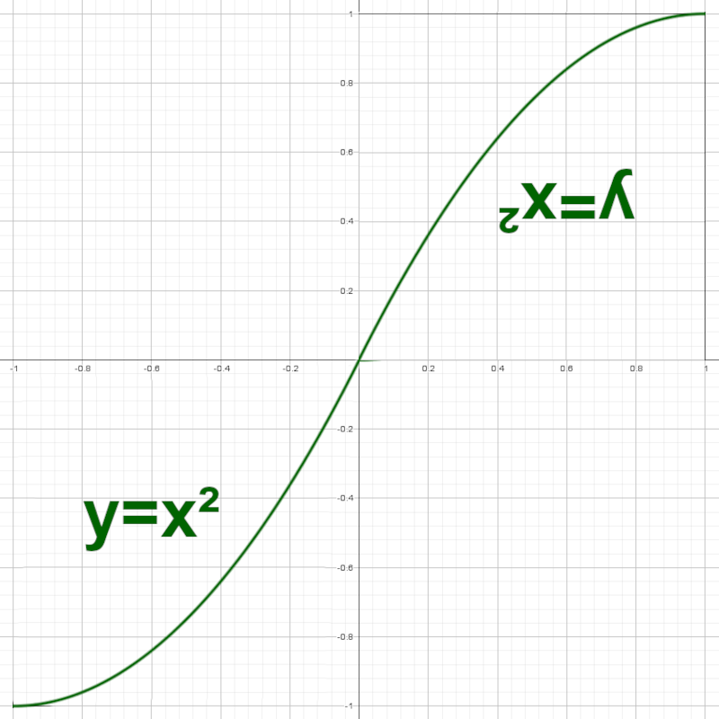 |
In short: take a power function between 0 and 1, and duplicate, translate and rotate appropriately to get a "s" shape.
The bottom left part of the curve can be expressed with the equation:
with -1 <= x <= 0
In this equation, the "+ 1" moves the initial curve (x²) one unit to the left, and the " - 1" moves the result one unit down.
CS stands for Curve Step.
The top right part of the curve can be expressed with the equation:
with 0 <= x <= 1
and C(x) = 1 - x
In this equation, the inner C(...) performs a symmetry around the vertical axis x = 1/2, and the outer C(...) performs a symmetry around the horizontal axis y = 1/2. Applying successively both of the symmetries results in a 180° rotation around the point (x, y) = (1/2, 1/2).
Note: In Shader Mixer, C(...) will be the custom brick (G) Complement Varying that I used in a previous thread.
That's a nice start, but I want to be able to change the sharpness with a parameter k such that when k is high, the transition is sharp, but when k is low, the transition is soft.
Luckily, a simple modification does it:
CSPowRight(k, x) = C(Pow(k, C(x)))
with Pow(k, x) = x^k
And now we can stitch the two together with the notation If([condition], [value if condition is true], [value if condition is false]):
Note: In Shader Mixer the brick Mathematical/Standard Functions/Pow computes Pow(X, Y) = X^Y.
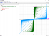
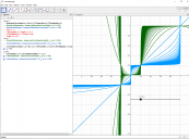
We can visualize what happens for various values of k in a graphing calculator (I used Geogebra):

In this picture, the diagonal line is what happens when k = 1: a linear transition.
When k increases above 1, the transition becomes sharper (family of green curves).
When k decreases below 1 (but always above 0), the transition becomes softer in the middle and sharper at the extremities (blue curves).
This is looking pretty great, but there are still two missing features:
- I want to be able to change the horizontal position of the inflexion point, in order to change how much Dark Color vs Light Color should be rendered;
- I want all this to happen between 0 and 1 both vertically and horizontally, because it makes building the shader a lot easier.
One possibility here is to scale both parts of the curve with complementary factors. Right now, each part of the curve fits in a square of side 1. If I scale the left part by a factor r < 1, and the right part by a factor C(r), then the combined curve will fit in a box of side 1, and the transition will still happen around 0 even though both parts will be unequal.
This can be expressed with the new equation:
In each branch of the If(...) expression, the internal division scales the curve part horizontally around 0, and the external multiplication scales the curve part vertically around 0.
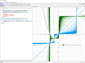
Here is a picture when r = 0.2:
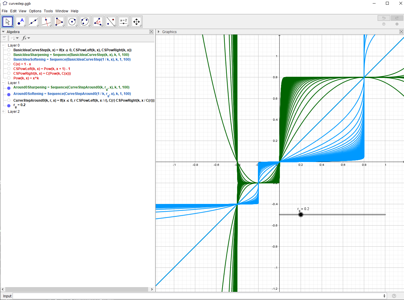
Note: To correlate what I wrote with the picture, you must focus on the interval [-0.2, 0.8] and ignore whatever is happening outside.
All that's left now is to move the box by translating both parts of the curve horizontally and vertically by an amount equal to the side of the lower left square, which is r.
Final equation:
In this equation, the "- r" moves the whole curve a distance r to the right, and the "+ r" moves the whole curve a distance r up. Both of these translations result in the combined parts fitting in the (0, 0) to (1, 1) box.
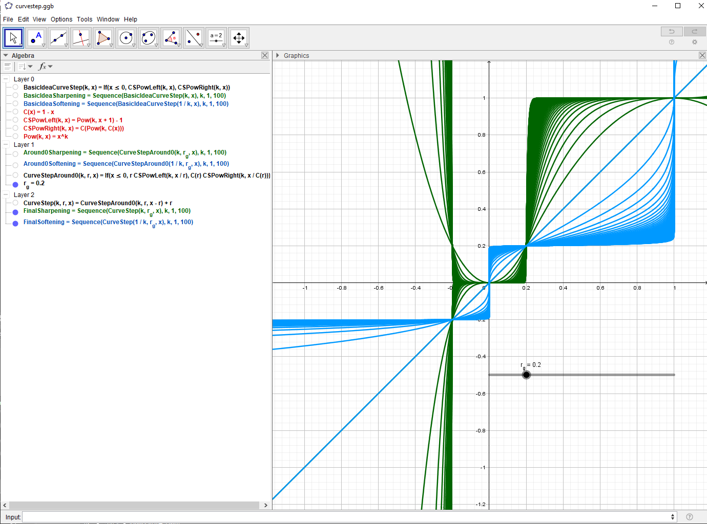
Here is what it looks like with r = 0.2:
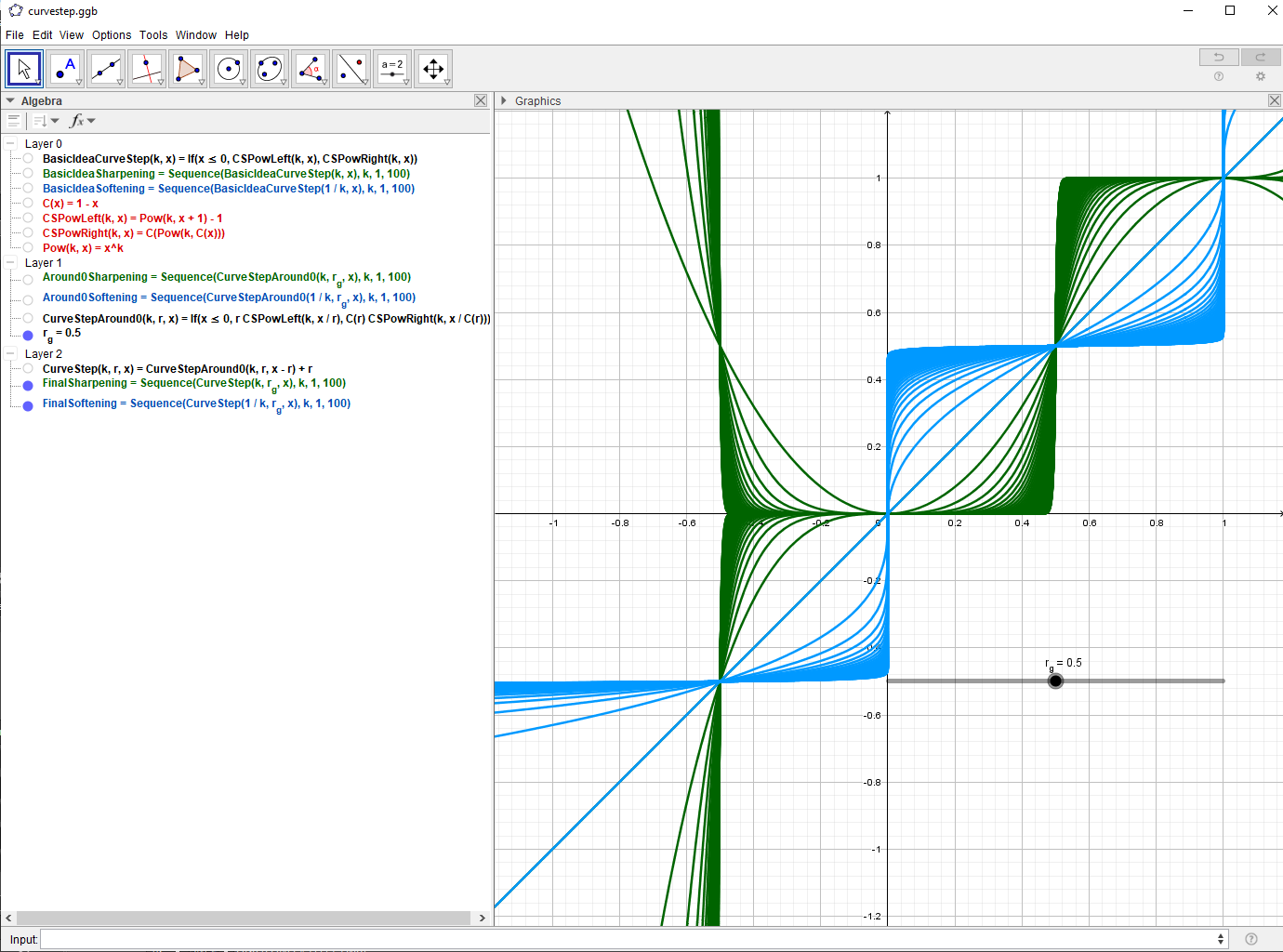
And we can change the value of r at will (between 0 and 1), for example r = 0.5:
b) The brick network
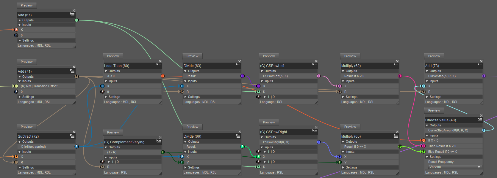
It looks confusing, but it is mostly a transcription of the formulas above, except for the Mathematical/Operators/Add bricks with a second argument 0, which I use as a convenient connection grouping trick that works both in RSL and MDL.
The inputs are on the left, and the output is the brick titled "Add (73)" on the right.
I won't detail (G) CSPowLeft and (G) CSPowRight, because they are just the implementations of the functions CSPowLeft(K, X) and CSPowRight(K, X) defined above.
(G RSL) Edges Mix
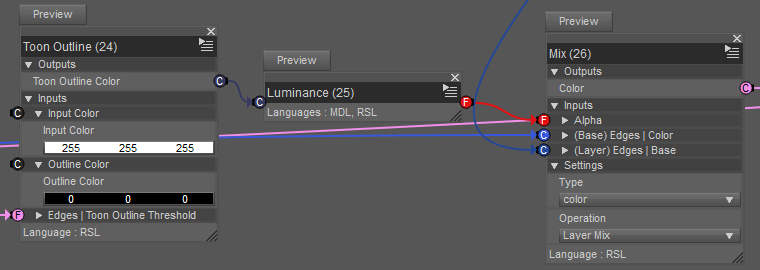
I used Geometric/Special/Toon Outline to save some time. I don't know exactly how it works, I'm guessing some kind of Fresnel-like method.
Since I couldn't figure out how to get the [Outline Color] pin to actually work (the outline is always black), I converted the output into grayscale to explicitly mix the previous color (output of (G RSL) Diffuse Curve Mix) with the user-defined edge color.
(G RSL) Glossy Mix
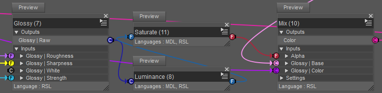
It's the same principle as the (G RSL) Diffuse Curve Mix but without the curve part, and with Lighting/Specular/Glossy instead of Lighting/Diffuse/Diffuse.
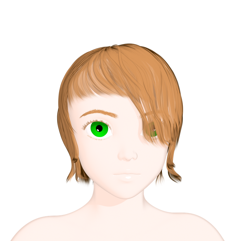
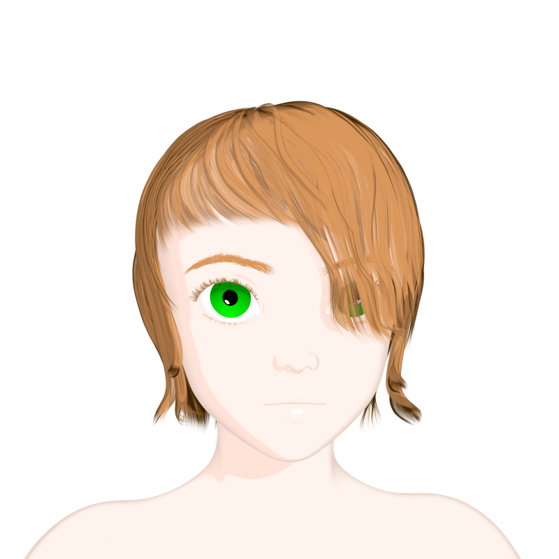
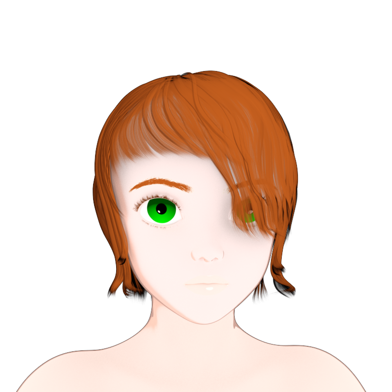
1.2. The results
1.2.1. Setup
Model: G8F with an anime head morph from sharecg (https://sharecg.com/v/88934/view/21/DAZ-Studio/Anime-Head-for-Genesis-8-Female-and-Male).
Hair: Aldora hair from Genesis Starter Essentials.
Lighting: one distant light with raytraced shadows.
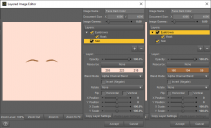
To add some of the details, like the eyebrows and the gradient in the irises, I use The Layered Image Editor to create layers with uniform colors, and I add a mask to the top layers.
For example for the face material I assigned a layered image to Dark Color and another one to Light Color. Each of these layered images is structured the same way: skin + eyebrows with mask.
The layers themselves don't contain any image, they are just filled with the appropriate dark or light color. The mask allows to change the color in a specified region.
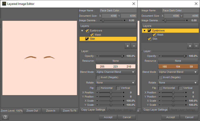
The eyebrows mask was created in Gimp from a Victoria 8 face texture because I was working with this model at the time, but any other face texture with eyebrows would do.
The irises mask was created in Gimp with two well-positioned circular gradients, nothing fancy.
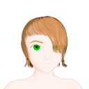
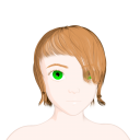
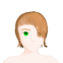
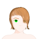
1.2.1. Render
Transition sharpness factor = 0.05%
Transition sharpness factor = 20%
So, it mostly works as expected, although I am not satisfied with the Toon Outline and Glossy bricks. I found them difficult to control and they don't give me exactly the result that I want, so next time I will probably just implement those features myself, like I had to do for the Iray custom version.
Rendering with shadows seems to have created some artifacts on the right iris, so I'll have to be more careful about that in the future.
Also, the hair is made of ribbons, which are disconnected open surfaces, and my edge detection shaders don't work on those, so I used only the shader I just described for everything, no geoshell. In the future I'll try to make proper toon hair.
End of Part 1 of 2


Daz 3D is part of 
Connect
DAZ Productions, Inc.
7533 S Center View Ct #4664
West Jordan, UT 84084
Licensing Agreement | Terms of Service | Privacy Policy | EULA
© 2026 Daz Productions Inc. All Rights Reserved.
Comments
Part 2 of 2: Cel shading with Iray
2.1. The idea
In this part, the key concept to understand what I was trying to do with the colors is the fact that, when a surface has both emissive and diffuse components, the final color is the sum of the emission color and the diffuse color. The emission color itself is self-contained, it is not affected by external objects. The diffuse color however is going to be black if there is no lighting, at least on a flat or convex surface. For example, if a flat surface has an emission color red (and a sufficient luminance to show it in render) and a diffuse color green, then:
- if there is no light (no environment or positioned light) or if the surface is in a shadow, then the surface will appear red;
- if there is some light but not too much, the surface will appear orange;
- if there is a lot of light, the surface will appear yellow.
So, on a curved surface, we can get a gradient from emission color to [emission color + diffuse color] depending on how lit each point of the surface is. And, for a distant light source, how lit a point is depends on its normal in relation to the light direction.
So, to get a gradient from Dark Color to Light Color using out-of-the-box Iray lighting, we need need a diffuse+emission material, and set the emission color to Dark Color, and the diffuse tint to the difference Light Color - Dark Color. For example, if Dark Color = (0.1, 0.3, 0.2) and Light Color = (0.1, 0.4, 0.6) then the emission color should be (0.1, 0.3, 0.2) and the diffuse tint should be (0.0, 0.1, 0.4).
In order to increase the sharpness of the transition (for example to get a manga or anime look with two colors) without precise control over the gradient, we can:
- increase the light intensity and rely on color saturation to get a flat lit region;
- or progressively make the normals uniform in order to remove the curvature-related variations.
2.2. Iray Uber Base
Initially I tried to do what I just explained with my custom diffuse emission shader (the (G MDL) MT Diffuse Emission brick). It had worked pretty well for my other experiments so far, and I was able to test the emission-diffuse gradient on simple shapes with primitive colors. But As soon as I started using non-primitive colors, I had to deal with persistent overexposure in the lit areas. I tried various alternatives and workarounds, but nothing worked until I tried to use the Iray Uber Base shader.
I didn't originally start with the Uber because then the diffuse-emission split has to be done by hand (or perhaps a script). But when I tested it, I was surprised to see that it did not have the overexposure issue. I still don't know why, and I will have to dive into the details of the shader later to figure it out.
2.2.1. Setting up the Dark to Light gradient
So, getting the gradient is relatively easy:
- deactivate the environement light (Render Settings > Environment > Environment Intensity = 0);
- apply the shader "!Iray Uber Base";
- set Cutout Opacity to 1 (the default is 0.5 making the surface semi-transparent);
- make sure that all the various XXX Weight properties are at 0 (glossiness might have to be added later on a case-by-case basis);
- assign your Dark Color to Emission Color;
- set the emission temperature to 0 (optional);
- set the luminance to a sufficiently high value (eg 50000 cd/m²) so that you can see your color in the preview or render;
- set the Base Color to the difference [Light Color - Dark Color]. You have to compute the difference for each channel (RGB) individually;
- add and position a light source (eg Distant Light) and adjust its intensity (eg photometric luminance 2000000 lm) until you can observe the correct* low and high colors.
* In 3Delight it is possible to render the colors exactly as they are specified, but in Iray, color values are more... aspirational. Still, it can get close enough to look decent.
2.2.2. Changing the sharpness
Changing the sharpness is more complex. The idea is to use a normal map that makes the normals point in a constant direction, essentially nullifying the curvature of the surface. I don't know how to do this inside Daz, so I used Blender to bake such a normal map.
Quick steps:
- Import the model into Blender.
- Add a plane rotated 90° around the x axis.
- Select the model and add a Data Transfer modifier. For Source, select the plane, and then select Face Corner Data / Custom Normals with a Mapping "Nearest Corner of Nearest Face."
- Make sure that the model UVs are in the (0, 0) to (1, 1) UV square. For G8 models this is only the case for head surfaces. If you want the torso for example, you have to move the UV island 1m to the left.
- Add and select a texture image node in each surface, creating the image if necessary (you can reuse the same image for multiple surfaces, for example to group the ears, lips and face onto the same image) with ColorSpace "Non-Color."
- With Cycles as the render engine, select Bake Type "Normal" and hit Bake.
- Check and save the images (normal maps).
Back to Daz Studio, the normal maps can be assigned to the Normal Map property of the Iray Uber Base shader.
When the Normal Map slider is set to 1:
- the curvature is invisible to the lighting, so the only changes are due to shadows, including self-shadowing, and ambient occlusion;
- the maximum intensity depends on how close the modified normals are to the light direction.
When the Normal Map slider is decreased:
- the color transition becomes smoother because the light can see more and more of the surface curvature;
- the lit areas can become lighter or darker, depending on the orientations of the original and modified normals relative to the light.
2.2.3. Surface details
I add the surface details the same way I do for 3Delight. In fact, the Dark Color layered images are identical. The Light Color counterparts however must be replaced with their differential versions.
For example, here is the layered image setup for the differential Light Color:
In part one I posted a picture of the setup for Dark Color, which is identical in 3Delight and Iray. The values were Dark Color (Skin) = (255, 223, 210) and Dark Color (Eyebrows) = (160, 104, 59).
With the differential values in this picture, we can tell that Light Color (Skin) = (255, 223, 210) + (0, 18, 25) = (255, 241, 235) and Light Color (Eyebrows) = (160, 104, 59) + (53, 36, 20) = (213, 140, 79).
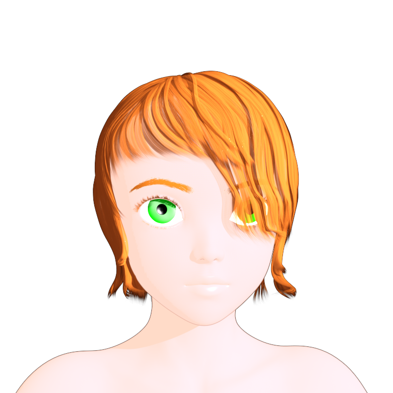
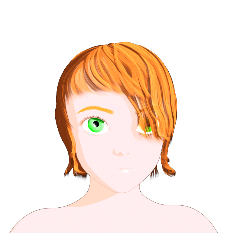
2.2.4. Results
Here is the result with Normal Map at 100% on skin and hair:
I don't didn't know what causes the jaggedness of the transition. Initially I thought it was the normal map resolution, but even with an 8k map the result is the same. However, the longer the render lasts, the more the jaggedness disappears. So I set Progressive Rendering > Rendering Converged Ratio to 100% to delay the completion, and it helped. Perhaps it would disappear completely if the render could be made to last longer, but I don't know how to do that.
Update: the jaggedness was due to the low mesh resolution, because Iray has to rely on the mesh geometry to cast the shadows. Increasing the SubDivision Level reduces the issue:
And here is the result with Normal Map at 10% on skin and 0% on hair:
I had some difficulty getting the glossiness right on the lips and eyes. For the lips I had to use the "Specular Lobe 2" feature. For the eyes... well, let's just say that it is good that the Aldora hair is so stylish.
2.3. Custom Phong shader
I made a custom shader because initially I didn't know whether or not I could achieve the desired look with existing features.
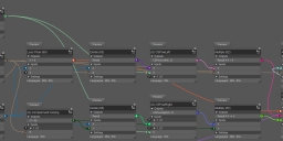
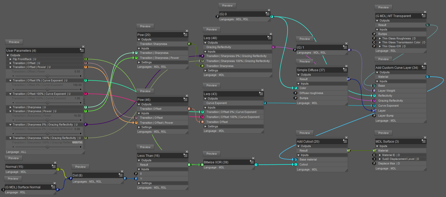
It is mostly identical to the 3Delight version, except that the lighting has to be calculated explicitly since I can't rely on the existing bricks that I know of. Here is the pipeline part with some of the inputs:
Note: Given the mess of colored lines going everywhere, I suggest to pay attention to the pin labels to understand the connections.
In order to avoid duplicating what I already said in part 1, I am going to focus on the differences.
There are 4 main operations in the pipeline, provided by:
- (G MDL) Diffuse Phong Curve Mix (instead of (G RSL) Diffuse Curve Mix)
- (G MDL) Edges Mix (instead of (G RSL) Edges Mix)
- (G MDL) Glossy Mix (instead of (G RSL) Glossy Mix)
- (G MDL) Split Color Diffuse Emission (New)
The 3 XXX Mix bricks require a unit normal which is provided by the normalized output of the Rounded Corner Normal brick.
The 2 (G MDL) Unit View Vector bricks are used to compute a light direction and view direction from the user parameters. I have described this brick in the thread on edge detection.
I have described (G MDL) MT Diffuse Emission in the thread on Inverted Hull.
(G MDL) Diffuse Phong Curve Mix
Instead of the Diffuse brick in 3Delight, here the diffuse factor is computed by taking the dot product between the surface normal and the light direction (one part of the Phong model), then clamping the result between 0 and 1.
The rest is the same as before, with MDL/Default Modules/math/Lerp instead of Mathematical/Mix.
(G MDL) Edges Mix
I won't spend too much time on this one because this was the purpose of the thread on edge detecttion, specifically RC-modulated Fresnel edges + RC edges.
(G MDL) Glossy Mix
This computes the specular part of the Phong model.
The custom brick (G) Reflect Direction Across Normal computes the value of the expression 2(D·N)N-D where N is the unit normal and D is the unit vector for the light direction.
Even though the result of the mix is binary (color on or off), I find this method easier to control than the RSL Glossy brick or the various Uber parameters related to glossiness.
(G MDL) Split Color Diffuse Emission
The Add bricks are just there to trick Shader Mixer into generating more user-friendly custom bricks than its creators intended.
The Lerp computes the amount of color to use as diffuse tint based on a user parameter.
Then the Mathematical/Operators/Subtract sends the rest to be used as emission color.
Results
Transition sharpness factor = 0.05%
Transition sharpness factor = 20%
For these renders, I adjusted the ratio Mix | Emission .. Diffuse for each surface to strike a balance between shadows (high ratio) and low overexposure (low ratio).
However, some of the shadows ended up lacking color. Setting the ratio to 0% would eliminate the shadows completely because everything would then be purely emissive.
2.4. Conclusions
Working with 3Delight was relatively easy. I didn't experience any major issue (DS crashing all the time is just part of my workflow now), but I am not entirely satisfied with my decision to use the default Toon Outline and Glossy bricks. In the future, I will probably update this shader to do the computations like in the Iray custom Phong shader.
For Iray:
- The Iray Uber Base option can deal well with shadows, but my custom shader can't.
- The custom shader gives full control over the gradient, theoretically allowing more than 2 main colors if needed in the future; by contrast, the Uber is restricted to two colors (although this can be alleviated somewhat with LIE), and all the channels of the Light Color must be higher than the corresponding channels of the Dark Color.
- The custom shader requires individual lighting for each surface, although this can be seen as an advantage for NPR. By contrast, the Uber leaves the surfaces open to interferences with whatever lighting and blocking elements are around in the scene.
- Sharpening the color transitions by forcing a constant surface normal seems like a dubious solution. The drawback is that if the light is not in front of the predefined normal, then the whole surface will darken. Perhaps this could be helped by having a customizable normal parameter, but it would require a new shader, not the Uber. That being said, getting cel shading right on faces generally requires adjusting the normals to bypass the geometric curvature, so the trick I used here isn't too far fetched.
- Sharp color transitions with the Iray Uber Base exhibit a mysterious jaggedness. (Update: the mesh resolution was too low, see above.)
Both Iray versions have pros and cons, while the 3Delight version is a kind of best of both world. I don't know if it is possible to combine the two Iray techniques into one shader. I need to figure out more about what Iray Uber Base does compared to my failed attempts, and perhaps I will be able to make improvements.
End of Part 2 of 2
very cool looking, quite a few people will be interested in this, especially if you decide to create a product
Thanks. I have actually been thinking about this, and I am considering submitting something to Renderosity, hopefully in the coming weeks.
I look forward to it. Iray needs good toon shader options like that.
Is this going to be using the built-in iRay toon shaders that nVidia had talked about last year I think it was?
No, I am currently not using built-in Iray toon shading features. The reason being that I do not know exactly what those features are, how to access them from Daz, or if they are accessible at all. If you have such information, please let me know.
For now, I am basically doing it the hard way: manually creating shaders from scratch to achieve the desired look.
There isn't a built-in toon shader, I think the question was about soemthing nVidia has been developing but if so, and if it's for Iray, I don't think it's available in DS yet.
Yes, nVidia announced it in their blog over a year ago, along with built-in "hair creation primitives" but I've not heard anything since.
I was able to fix some of the issues with my Iray shaders, although I still don't have a completely satisfying all-in-one solution.
In this post, I will present two new shader: a replacement for the Iray Uber Base option, and a special light modulator that applies an effect on the inside of a geoshell while removing the outside.
Finally, I will show a nw render before concluding.
A) The new shader
I will explain how I fixed the issues and then give a partial view of the shader.
A.1) Overexposure
I compared a simplified shader (Emission Color = Dark Color, Diffuse Tint = Light Color - Dark Color) to an Iray Uber Base.
My strategy was to remove the connections and bricks in the Uber, one by one, until I could see the overexposure in the Iray preview.
However, there never was overexposure, and I reached a point where the only meaningful difference between the two shaders was the Mathematical/Operators/Subtract brick.
It turns out that the color values entered by the user are immediately gamma-corrected before being passed to the brick, so the subtraction was being done on gamma-corrected values, and the computed tint was incorrect, resulting in overexposure in my shaders.
The fix was to undo the gamma correction before computing the subtraction, and then re-applying it. In the process, I also felt that the emission color was rendered differently, so I decided to add a different gamma correction to the emission color, independently of the subtraction. I think it helps get the colors closer to what I enter manually, although they are still not identical.
The gamma operations are done with a simple Mathematical/Standard Functions/Pow.
I used as default 2.2 for the diffuse gamma, and 1.8 for the emission gamma (found with trial and error). Although in practice I sometimes have to change the emission gamma to get a better result.
I will show the brick network in section A.3.
A.2) Normal override
It is no longer necessary to use an external program to create a special normal map. I now use the brick MDL/Default Modules/base/Blend Normals to alter the current normal with a user-provided overriding normal.
A.3) Updated shader
Even though it looks a bit different than before, it is actually the same pipeline.
(G MDL) Diffuse Emission Edges Mix is positioned before (G MDL) MT Diffuse Emission because I am doing the edge detection using my own method (see the Phong mix shader in my earlier post) and I needed to blend the tint and emission color properly. Perhaps I should have made the edge detection brick as a MT → MT transformation brick so that I could put it after, for clarity.
(G MDL) Light Color Diff
As I explained earlier, I use the user-provided diffuse gamma value to undo the correction before the computation, and then to apply the correction to the result before transmitting it to the next brick in the pipeline.
(G MDL) Diffuse Emission Edges Mix
This updates both the tint and emission color based on the detected edges and the user-provided colors. The custom brick (G) Edges Opacity is the edge detection that I already explained before.
Remaining bricks
The MDL/Material Editors/Top Coats/Add Weighted Top Coat is used to add glossiness. I use it pretty much as-is, and you can see the result on the hair of the character in the picture at the end of this post.
Finally, the opacity and updated normals are now managed by a MDL/Material Editor/Uber Add Geometry. In previous versions, I was using the (G MDL) MT Diffuse Emission for that, but I think it makes more sense to have the cutout at the very end.
B) An alternative to normal override: the Fresnel Light Modulator geoshell
B.1) The problem
This one is tricky to explain. I wanted a better way to change the sharpness of the color transition, and I thought that perhaps the Fresnel effect (using MDL/Material Editors/Layering/Add Custom Curve Layer) could help.
Since the lighting intensity only depends on the normal orientation (for a distant light source), the idea was to get the Fresnel effect to reduce the lighting on grazing normals, ultimately achieving control over the color gradient (it's like being able to modulate the output of the Diffuse brick in 3Delight).
But I couldn't just attach an Add Custom Curve Layer to the main shader because the Fresnel effect applies to all rays, including camera rays. I don't know if this is actually how it works, but what I mean is that it affects both the light arriving to, and the light leaving, the surface.
So, if we do simply do that, we can observe a sharpening, but also a Fresnel edge wherever the surface normal is at a grazing angle relatively to the camera.
In the table above, the second picture shows two effects of introducing a Fresnel effect directly in the pipeline:
- a sharpening of the transition from the dark color (bottom left) to the light color (top right);
- a Fresnel edge all around the sphere, particularly visible in the lit region (top right).
The sharpening occurs because the Fresnel effect affects the light reaching the surface.
The edge effect occurs because the Fresnel effect affects what the camera perceives.
The big problem with this is that increasing the offset of the transition requires thickening the edge, leaving less and less space for the lit region.
Furthermore, the Fresnel effect causes a darkening of the lit region near the edge, which is literally the last place that should darken.
How can we get the sharpening without the edge effect?
B.2) The solution
Now is a good time to remember my experiments with the Inverted Hull. If I could create a geoshell that is transparent with the Fresnel effect on the inside, and at the same type fully transparent with no effect on the outside, then I might have the effect that I want.
Here is the shader:
It only uses bricks that I already described.
The bottom part computes the oriented surface normal (texture U x texture V) to cut out the outside of the geoshell.
The top part creates the Fresnel effect, which will be only visible from the inside (because the outside is gone).
Note that it is only a half-sharpening, because the lit area is not touched. It's more like extending the dark region with an edge of customizable sharpness.
I was hoping that using a high index of refraction could help eliminate the lighting gradient in the lit area, but it doesn't really work. Changing the IOR has some kind of effect, but I am not sure what it is. I am pretty sure however that it is not what I want.
In any case, even though it is not perfect, it is a nice alternative to the normal override method because it doesn't require manually passing a normal to the shader.
For comparison, here is the sharpening obtained with the normal override method:
C) Iray Render
Comments
All the surfaces (skin*, hair, clothing) use the shader described in section A.
Additionally, G8M has a Fresnel light modulator geoshell (so it only affects the skin*).
* By skin I mean all the body surfaces: skin proper, eyes, teeth, etc.
I wanted to see what the shader would do on a muscular figure, so I cranked all the bodybuilding/tone dials to max. Consequently, the shape is a bit weird here and there, and the right arm looks wrong. I couldn't really get all the edges that I wanted, but overall I am pleased with the result.
I had to use the Movement dials of the hair because the tips on the left side of the head had an intense glossy reflection, probably due to the geometry of the hair.
For the boxers:
- I did some surgery to hide a weird fold that was messing up the colors.
- I used normal override at 25% only because I thought having some shading looked better; but it is possible to go above and get a two-color flat shading.
- Giving the waistband an orange color was very difficult because the render kept oscillating betewwn black and yellow. Something weird seems to be going on with some colors, but I don't know what.
Credits
The model is G8M with morphs from Genesis 8 Male Body Morphs.
The pose is from Z Body Combat - Poses for Genesis 8 Male and Michael 8.
The hair is Basic Hair for Genesis 2.
The clothing is Basic Wear Boxers from Genesis 8 Starter Essentials.
D) Conclusions
Just like the edge detection, my method for cel shading in Iray results in several shaders with overlapping and complementary features.
Each shader requires its own set of compromises, but I think it is possible to get decent result by carefully tuning the parameters for each surface.
Do keep an eye on the chnage log as there have been several modifications affecting Shader Mixer bricks http://docs.daz3d.com/doku.php/public/software/dazstudio/4/change_log
Thank you very much for this important information.
I use DS 4.15.0.30 and I can see for example that some of the bricks that I use, like DzMdlColorInput1, are removed in DS 4.15.1.87.
So I installed the DS public beta and tested my scene. Luckily, everything appears to be working.
I checked the shaders and DzMdlColorInput1 was automatically replaced with DzMdlColor, in accordance with the change log.
In the future, I will do additional tests using the public beta. But if I do encounter incompatibilities, perhaps I will have to make multiple versions, I'm not sure.
A) Potential future product: KFR6 Toon Shaders
I uploaded my files on Renderosity.
The Pending Products table indicates that the status is "Review." I don't know if it means that they are going to review it or that I have to review something that I missed. I guess I'll know in a couple of days.
My main concern is that I have no idea what it will do with an Nvidia GPU. And when I use my shaders, DS tends to crash randomly. It's not bad enough to prevent progress, but it is annoying.
Here is a recent render using the Iray shaders:
Credits:
Comments:
Getting the colors to not look horrible was more difficult than I would have liked. The good news is that, with dedication, it is possible. But I need a better long-term solution.
I used a low SubD level for the displacements (water and sand) because I thought it looked more stylized.
Those dark spots on the sand are actually details of the displacement map. In retrospect, perhaps I should have used the water displacement map on the sand and the sand occlusion map as a L.I.E mask for the color blending, because then I would have had better control over the shapes and colors.
I wanted the abs to pop more to show the bi-color glossy effect, but the morphs I have just bulk up the whole body and then weird things happen around the neck.
I had some difficulty with the shading on the legs. And trying to add some gloss made them look either really bad or almost photoreal, which was not what I wanted. I think it's because there might be too many details around the knees and ankles.
B) The mysterious Nvidia Line/Toon Renderer
I tried to look more into it but, aside from the old blog post, I couldn't really find much more than their promotional page with a picture:
To sum up the clues that I have found so far:
Based on that, my guess is that it is not a shader-level feature, but rather a post-processing tool.
OK, thanks
KFR6 can you please provide more information on product installation. I am getting missing files errors on almost everything I try. Thanks.
シェーダーをダウンロードさせていただきました。
現在大きな問題となっているのはアウトラインを使用するなどの際に
カメラアングルを変更すると外が黒くなる点です。
シェーダーリセットを使えば解決するのですが、それではImage Seriesでタイムラインレンダリングを行う際にかなりの不都合が出てしまいます。
I have downloaded the shaders.
The big problem now is when using strategies, etc.
The point is that when you change the camera angle, the outside turns black.
Using a shader reset would solve this problem, but this can be quite inconvenient when doing a timeline marathon in Image Series.