Which lofting method is used here?
 WsCG
Posts: 391
WsCG
Posts: 391
Hi all,
So, I'm trying (desperately lol) to find tutorials to help me understand how Carrara works. I keep running into the same situation, where I think I understand how to do something in the program, only to hit a wall when I try to implement what I (think I've) learned... and end up not being able to figure it out.
So the latest is trying to create a simple wine-glass using lofting. I found a great video here
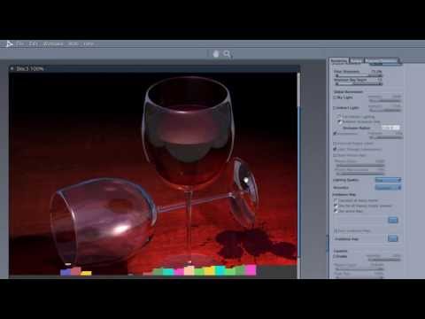
He shows that he's created it with a spline. I thought I understood what he's doing (I've done lofting in other programs, so I understand how it works), but once again... Carrara throws me a curve ball, and I can't for the life of me figure out what's going wrong. How does he get the exact replica of the wine glass on the ground and side like that? I can't get that to happen, and I've tried selecting everything in the drop-down for the different Extrusion options. I get the wine glass shape on the ground and then just a straight line with a bunch of points in it on the side wall. Further, when I try to modify the points on the side wall, it messes up my point positioning on the ground.
Thanks.
Daz 3D is part of 
Connect
DAZ Productions, Inc.
7533 S Center View Ct #4664
West Jordan, UT 84084
Licensing Agreement | Terms of Service | Privacy Policy | EULA
© 2026 Daz Productions Inc. All Rights Reserved.
Comments
Lathe is what you need.
Lofting,. comes from shipbuilding where a ship was originally constructed in a Barn type of building called a loft,. hence lofting.
Lathe comes from the process of turning (spinning) a shaft of wood in a lathe (like a drill) and using a cutter, to shape the wood as it's turned
When you use the lathe tool in the vertex modeller in carrara,. you begin by creating the outline Shape you want,. ,. then select the lathe tool, and select the central edge you want to lathe around.
There are options in the right hand panels to adjust the amount of segements in the lathe.
once you've made any vertex model,. you can add subdivision smoothing levels to create a smoother or more defined model,. so you can begin simple,. add more edges as needed and smooth to get the shape you want.
hope that makes sense
Pics to help
Mark Bremmer uses the spline modeler in that tutorial. Carrara also has a vertex modeler, which is most similar to Hexagon, etc. Whatever method is used to make the glass (spline or vertex), to get a second object the same as the first, return to the assemble room and use the EDIT: DUPLICATE choices from the top menu, or use the hot keys CONTROL D (CMD D on a Mac). A second object will appear in the scene. To rotate, translate, or scale anobject, you can use the menus on the left side of the interface, or you can use the hot keys R, T, S respectively.
1 - I made a spline wine glass followig the basic method of Mark's tutorial.
2 - returned to the assemble room. The spline objectcomes in sideways.
3 - I selected the spline glass and used the rotate menu on the left side to get the spherical lines surrouning the glass. Holding the shift key, I dragged the rotate line to reposition the glass 90 degrees. (Could use the hot key R to rotate if you prefer the Blender world).
4 - I selected the wine glass again. I went to the top menu and chose EDIT: DUPLICATE. Could have used the hot key CONTROL D. A second wine glass appears identical to the first.
5 - I used the rotate, translate, and scale functions to reposition the second wine glass. Holding the shift key while rotating will result in 45 degree increments o you can get to 90 degrees to lay it sideways.
To do something similar in the vertex modeler, use the polyline tool to draw the cross shape you want to lathe. To d so, inserta vertex object (sends you to a modeling room). Choose the front camera view (or top, or whatever, but choose a directional camera so the drawing planeis flat and in the direction that ou want). From the top menu of the vertex modeler click the polyline tool. Draw the outline of the shape you want including a line around which you want the shape lathed. From the top menu, choose CONSTRUCT : LATHE and then it will prompt you to click the line you want to lathe around. You can then use the plus or minus keys to add or subtract detail. Click ENTER to finish. You can select any point or polygon tobring up the modeling menu and check the SMOOTH option on the right side if desired.
Then duplicate and rotate as above.
Thanks for the feedback everyone
Hi there.
You're using exactly the same process I'm looking to use to create the wine glass.
To be clear, I'm not having trouble duplicating the wine glass. I'm having trouble creating it in the first place, using the spline modeler. I know how to create an object using lathing in the vertex editor. I'm trying specifically to learn how to use the spline modeler in this case.
In your Spline01.jpg image, you notice how you have the profile on the floor plane (green lines) *and* the side plane (blue lines)? That's what I'm having trouble doing. I can get the profile on the bottom plane, but I don't know how to duplicate that on to the side one, so that both profile shapes are identical, and the wine glass comes out correct.
I'm completely stuck at trying to do that. Nothing is working.
Also, now I'm having an additional problem where I can't move the points along the X-axis on the floor plane. It will only let me move them along the Y axis. Similarly, I can only move them along the Y axis on the side plane, and not the Z. I was able to move them around on both axis just fine earlier. No idea what's going on now.
It's like the program is deliberately messing with me at this point lol.
I recorded a quick video to show what I'm talking about.
In that video, I'm trying to move the points up and down on the vertical plane, and side to side on the floor plane, and it won't let me.
Thanks!
Hi Mitovo, I just tried duplicating your problem based on your video example and, based on your extrusion envelope, I think you need to have some kind of geometry in the cross sections to move the points. . If the extrusion envelope is set to "none" I can click away as many cross sections as I want and move the points freely. If set to "Symetrical", "Symetrical in Plane" or "Free", and the cross section contains no geometry, the movement of the points is limited to the extrusion axis, or whatever it is called (making up terms here, lol). So to test I just copied and pasted a circle into 4 cross sections and could freely move the points, but if the cross section contained no geometry I couldn't freely move it if the Extrusion Envelope was set to anything other than "none". Hope that makes sense (it barely makes sense to me...).
Hey there, DesertDude,
Thanks for trying it out as well.
So, that leaves me wondering, then, how Diomede and Mark Bremmer are able to create the spline shapes they have. That's what I'm stuck trying to figure out. I've not been able to do anything like that. I can't modify the existing lines, and I can't add any new lines.
Diomede, how are you creating those profile lines in your pic?
Mitovo, I'm not familiar with the tutorial you are using, but you can only create "geometry" in the cross sections themselves using the tools - you have a pen tool, a shapes tool, a text tool, and some tools to add, delete or convert points. See attached picture. In my example, I used a circle in cross section 1, the pen tool to create a crappy shape in section 2, the rectangle tool in section 3, and the pen tool again in section 4.
Yeah, that's what I'm trying to do. I'm unable to move the points off the Y axis to create anything with them, as in my video.
I use the spline modeler so seldom that it always takes me a few minutes to figure it out each time. If you are making a symmetrical object you can just choose the Symmetrical Envelope option and you only need to draw the shape on one plane - Carrara will duplicate it to the other. I think you need to start out by drawing a shape on the first section plane though so that Carrara has a basic starting shape to skin your profile with. I tried to make a quick glass and managed something vaguely martini glass-like (I don't drink wine ). My steps are below.
So... starting from the beginning:
I attached some screenshots to help clarify (I hope).
Be sure that your last point ends in the middle. When done you can select some of the points and use convert points to add little handles to them - you can then drag those handles around to smooth transitions and make rounder shapes if you want (like the Pen tool in Photoshop if you are familiar with that).
P.S. - Another screen grab...you select your points along that extrusion axis and go to the menu Sections>Create to create your cross sections. You can then draw on those cross sections and your shapes will be "lofted" from one section to the next. You can then select your cross sections by number using Sections>Go To.. Lots of options to tweak how that is done, look to the right side of the interface under the General tab when using the Spline Modeler.
Woops, was typing as MDO2010 was writing a much cleaner explanation.
Using cross sections like this and drawing each section is another way to do it - I find it a bit hard to work with personally and usually just use the method I outlined above (or else draw out my profiles in Photoshop and save as .ai files, which you can just import straight into the spline modeler - IIRC Mark Bremmer goes into that in more detail in the tutorial linked in the OP).
Heh. For values of "cleaner." Tried to write with a mouse on my last screenshot and it looks like I'm having a stroke.
Good points...no pun intended. I should check out the tutorial, it's been a good long while since I have used the Spline Modeler for anything other than super simple stuff. Plus, it seems to be my nature to do stuff the hard way.
Lol!
Wow, sorry, I've been watching American football instead of paying attentionto the thread. Give me a few minutes and I will post a quick spline modeler example, which seems to be the immediate issue. There is almost always more than one way to do something in Carrara so I won't be claiming that my way is THE way, but I should be able to put something together shortly - unless my football team starts doing something exciting.
I was putting a quick workflow together and realized I was just repeating what MDO2010 wrote above.
Hey all... Thanks for the replies and demonstrations! Sorry for the delayed response; life's been keeping me distracted.
I'll have to give MDO2010's demonstration a go.
It might well end up that I stick with the vertex/lathing approach. I'd just like to become familiar with the different options, so I can decide which approach would be easiest/best (for me) to use in the future.
The tools are there, may as well become familiar with them, eh?
Thanks again!
Miltovo, I don't know if you have peeked yet but in your browser tab look under Objects/Basic Objects. There you will find mostly spline objects... there is even a wine glass called Lathed 1. Perhaps just studying and messing around with it you might learn where your problem lies. Check out the other spline objects also.
Thank you for asking... this has been helpful to myself since I use the vertex objects and want to learn more about spline editing.
Lotsa luck, Have fun.
Hello!
Actually, I think it's finally "clicked" lol. I was going about it backwards before. I didn't realize you only had to work on a single spline (in symmetrical mode anyway), and the program does the rest. So basically, I was fighting the program.
I think the problem was that I'd been watching several different videos on using the program, and I was getting the different methods mixed up/confused. So, I was basically trying to work in several different modes at once.
Hooray for learning lol
Anyways, thanks again everyone for the help!