Dealing With Non Co-planar Faces?
 Hermit Crab
Posts: 877
Hermit Crab
Posts: 877
I have to admit that I'm not sure what non co-planar faces are but think that I've managed to create a few in a model I'm working on.
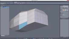
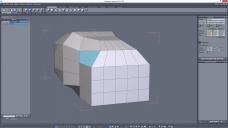
For clarity, Ive just made a meaningless shape to illustrate the kind of thing I've discovered in my model.
The first picture shows a face selected which looks fine from some angles. The second picture shows what is really going on with that face. In the second picture I've selected another face which has a similar flaw even though it looks OK.
In the model I'm working on, the problem arose from trying to follow reference images by eye - just pull a little here, shrink a bit there... Then the faces ended up non-coplanar (if that is the term).
Is there a recognised habit, to get into, to avoid this? Do they cause big problems when rendering textured models further down the line?
Daz 3D is part of 
Connect
DAZ Productions, Inc.
7533 S Center View Ct #4664
West Jordan, UT 84084
Licensing Agreement | Terms of Service | Privacy Policy | EULA
© 2026 Daz Productions Inc. All Rights Reserved.
Comments
You have got a couple of terms mixed up:)
Co-planar faces - that is faces which occupy the same space - must be avoided. They are easily detected by a sort of "shimmer" look and will cause rendering artifacts. When this is caused by, for instance, extruding from the same edge twice, it will make non-manifold edges, which are fatal in Hexagon.
The face you illustrate is non-planar - one of the corners is not on the same plane as the the top opposite corner. These could give rendering artifacts, depending on how far out of alignment they are. You can detect whether this will cause a problem by seeing a "shadow" on part of it. Also best avoided, but often not possible and not a problem if there is only a small difference in alignment. One way to fix that is to make a loop cut so that there is a smaller difference between the alignment of the corner verts. Another way is to connect corners to make two tri's. Tri's cannot be non-planar.
The one you illustrate can be easily fixed by moving the vert of the top back corner to match the front one, so getting the slope to match.
Thanks for that, Roygee. Once again you've been very helpful to me. I guess I should think in terms of sheet steel - if a sheet would need a fold in it then think of which way to avoid it.
You may remember that I started a military vehicle last year. It somehow got abandoned but I now want to complete it and have been looking at chamfering edges, reducing polygons, re-working more or less everything. I'm about to resurrect the thread.
Here is an image of the re-worked turret. You will see the flaw in one face. That face actally had five sides, which may have been the problem. I've since made it into two faces.
Forgot the image!
The analogy to a steel sheet is spot-on. Something which we often forget is that there are no actual bends or curves in polygonal modelling - it is all straight lines, so when one of the verts in a quad is out of kilter to the other three, it is like trying to bend the poly, which just doesn't work!
Glad you are resurecting your model - it was getting along nicely and the latest post looks like you have made some real progress - as always, I'd love to see the wireframe:)
When you have such non-planar polygons, Hex can automagically slice them into two triangles which are ALWAYS planar. Under the Utilities tab you will find the tool to do that, see the screengrab below. The top one from the dropdown is the one you want.
Thanks, grinch2901. Hexagon continues to amaze. I'll have a go with that.
I know this is a somewhat old thread, but, I'm bored, can't sleep, so... congrats on receiving a bit of bloviating from some anonymous dude. :)
AFAIK..
A "non-coplanar" face is a face that is not "planar", occupying the same relative plane, as its neighboring faces. Non-coplanar faces are common. For instance, in a cube, how many faces are "planar" to each other? The answer - None. You can't take the plane generated by one face and extend it to another face that shares that same plane. For instance, if you had one face and perfectly bisected it in two with an edge and generated vertices, it would equal to two perfectly co-planar faces. Unifying co-planar faces is a way to reduce geometry in 3D modeling.
A face that is not "planar" is a face where one or more its vertices is not aligned on the same "plane" as the rest. This is a bit difficult to describe, but let's take a tri-gon, the simplest "face" possible. It has three points and, by definition of geometry (for this purpose) all of them are on the same "plane", calculated betwen the three vertices, the smallest group of vertices able to form one face of a 3D model. Now, add a vertice to that to make it a "quad" and then move that vertice +/- relative to the original "plane" that the three other vertices formed. What ends up happening? The face becomes "warped", somewhat, resulting in a face that is not... planar. It's bent!
So, "planar" relates only to one face, "co-planar" is about comparing one face to another. Technically, two faces that have all the same coordinates and are both, themselves, "planar", would be perfectly "co-planar" to each other and rendering them would likely cause issues like shimmer, etc, as the renderer tries to render it in real-time and gets confused, strange occlusion effects in most full renders. (Double-faced modeling used to be popular in certain applications, due to how normals used to be rendered. But, it's... disgusting and isn't normally done anymore..)
In inorganic modeling, like for hard-surface objects, man-made constructions, a door, a child's toy block, a metal chest, etc, "co-planar" faces are very common as there is generally not a lot of soft, rounded, swirly, squishy, organicky sorta stuff going on. So, for instance, you could make a chest to store toys in with 5 quad faces for the body of the chest and one to five faces for the moving top. Let's say, though, you weren't going to animate it and a texture-monkey is going to do their magic on it and create a texture that makes it look like a chest with a lid. OK, so, now you have these ten faces sitting there, doing nothing. What do you do? Meh... merge all the "co-planar" faces, the faces that share the same plane with their neighbor. And, if the chest originally had five faces for the bottom and five for the top, how many faces would it now have? Yup, it would simply be a cube, after it was merged (And you didn't already split it up, right? :) ) which would be 6 faces. Job done, time for a beer...
In organic modeling, like with human figures, detailed plants, vases, animals, critters, liquids, squished up monkey-guts, etc... non-co-planar faces are extremely common. How many co-planar faces are likely to be in a detailed model of monkey-guts? Err.. One set, that I can think of, offhand. (The razor-blade...) In short, non-coplanar quad faces are the general "rule" of the day for organic models. And, with a detailed organic model, there can be a bunch of them. However, what's important is how "non-planar" the faces are. A quad face that is so non-planar that it "folds" itself is... bad. A quad face that is non-planar but only has a slight deviation from a plane relative to any set of three of its vertices is not, necessarily, bad. (It's worth mentioning that trying to generate some automated feature that would, somehow, make all faces in a model perfectly "planar" while still keeping the details of an organic model is tricky.)
So... are non-planar faces "bad?" That depends on your renderer and your application. (Rule #1 - Always model for your renderer/application! The renderer/app will dictate your geometry needs.) Most renderers have a "smooth shading" effect which can smooth edges and such so that whether or not faces, themselves, deviate in their planarness won't matter much for an organic model - It'll all come out in the wash. (And, it'll all come out in the level of detail/resolution, as well.) In fact, it's fairly common that certain deviatsions are accepted and expected for individual faces. For an inorganic model, that all depends on what your final rendered product is supposed to look like. If it's a straigh-edge ruler, then bunches of faces better be co-planar!
And, for most game models, faces are all tris, anyway. So, in that case, there's no such thing as a non-planar face. :) (Game renderers generally use trigons because it allows for quicker rendering of faces and calculated effects that only have to deal with three-vert faces to work with instead of four, even though this makes the model size a bit larger in some cases. The premium is on shaders and effects, not-necessarily, geometry size.)
On the OP's model - Whether or not that one non-planar face will be a problem is dependent upon the renderer. However, because of the low-poly nature of the model, all faces should probably be planar.... but, not co-planar, 'cause then it would just be completely flat and texturing it to force it to look like it was supposed to would be a real pain and someone could get hurt... :) (I know little about what application the model is intended for.)
Sorry for the non-brevity. I have an excuse, but it's probably only valid to me.
Single-malt, hopefully:)
Just to throw a spanner in the works - all renderers turn all quads into tri's at render time. So, why do they still retain some strange shading artifacts if all tri's are by defintion tri's?
https://support.turbosquid.com/entries/20210833-Coincident-Faces
Edit: After doing some ruminating and research on the internet, it appears that there is some conflict regarding the correct use of the term "coplanar". In general, in 3D modelling, the term more commonly refers to two or more polygons which occupy the same 3D space. i.e. coplanar in all three axes. Also referred to by Turbotsquid as "coincident", which is probably more descriptive. These are bad topology and cause z-fighting (that shimmering look)
The term is also used by some to refer to polygons which are on the same 2D plane, i.e. coplanar in two of the three axes, but this is not a very common usage in 3D modelling, more used when referring to mathematical functions.
Hexagon itself actually uses this last definition. If you draw out a grid and apply the "merge coplanar faces" it will merge all the faces into one, although none are coplanr in all three axes.
Thanks, guys, for the interesting follow-ups to the original replies and for research done on the question.
Morkonan's point that the problems caused depend on the final renderer is also of use. It must be the modeller's responsibility to avoid these faces if the work is intended to be sold, I suppose.
I've done some more work on the military vehicle and will update the thread with some images.
A question which has arisen for me concerns n-gons. If a rectangular face needs an extra vertice on one edge in order to join to an edge on an adjacent face, does the rectangle become five-sided? If it does, as I suspect, does it matter in such a case?
Yes, it does - a"side" being defined by an edge, which is the connecting line between two verts. How about giving an example so we can suggest methods of getting the join more efficiently?
Here is a problem from my vehicle - it's a flared-out part of the body under the rear wing.
I want to have a vertice mid way-down the long edge so that I can weld points and get rid of the upper triangular part of the odd-looking quad. I thought of tesselating the rectangular face into four faces. Then I would weld points. The down-side is that I would be left with a large triangular face (which is accurate for the model). It will be well out of sight and shouldn't matter too much.
Maybe I've found my own answer!
If I do this I'll probably have about an hour of tweaking to avoid ....coplanar bent faces !
Good solution - concave polys are not good topology:)
BTW, you can fix the n-gons on what I take is the transmission using the edge reduction technique shown in red on this pic - you can also use the same technique to reduce the number of unneccessary edges flowing from the wheelarch.
Thanks for the great tips, Roygee and for the trouble you went to in providing images. I feel that, as far as learning Hexagon goes, I'm getting to the stage where tips such as yours will stay with me.