How do I handle booleans when exporting to .obj?
 Ademnus
Posts: 744
Ademnus
Posts: 744
How do I deal with this?
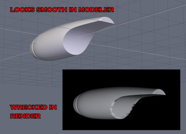
cas.jpg
1209 x 870 - 172K
Daz 3D is part of 
Connect
DAZ Productions, Inc.
7533 S Center View Ct #4664
West Jordan, UT 84084
Licensing Agreement | Terms of Service | Privacy Policy | EULA
© 2026 Daz Productions Inc. All Rights Reserved.
Comments
Thou doesth not use Booleans ;-)
They are way more work to fix than is worth the time effort and it takes awhile to grow hair back in.
I think some use one of the options to make everything tris or something but those again can cause issues.
Edit to add pic ... very rough draft of where the tess lines need to be. Working from a Boolean cut though tends to result in an unusable file.
Thanks for the reply, I was starting to wonder if anyone had even seen the post.
I know, I want to avoid booleans, but I just cannot seem to make that shape the way a boolean can. Let me also give you some background to this question.
I once asked how to do this, and I was told "always use boolean cuts."
I once asked how to fix the problems that arose and was told "never use boolean cuts."
I once told someone "I guess the best answer is to not use boolean cuts" and was derided by an entire forum.
I once asked how to make this shape best and was told "boolean cuts."
So I looked at some of the better models out there and it is clear from examining the mesh they used boolean cuts. So I looked for a tutorial and they used boolean cuts. So I used boolean cuts and this is what happens when I render it.
So now I ask how to fix it and I'm told "don't use boolean cuts."
Hehe I think this must be a modeling hot button issue.
So, ok, clearly there is no definitive answer and the modeling world is divided on the eternal question popularized first by Shakespeare, "To boolean, or not to boolean -that is the question."
If I go your route, to which I am not opposed, how do I really make that shape happen? With nice crisp lines? Here's one I'm working on now.
https://i.imgur.com/OPG7mmd.jpg
I made the shape, sort of, but it absolutely lacks the proper shape I seek, as reflected in the picture I showed at the top of this thread. I can't seem to figure out how to achieve it without the cut. I'd prefer to not use the cut, but I can't get the right shape. If I use the cut, it isn't worth rendering. I'm open to either way, so long as I can make it work. I am totally open to tutelage on this.
OK, n00b to Hexagon here, but I'm not new to computer graphics in general.
From a subdivision surface modeling perspective, I think the problem with the boolean operations is that they leave you with "poor topology" on the mesh. Things aren't quads anymore. There are no nice loop rings of quads on the model anymore, at least in the area where the boolean operations have been applied. Boolean operations are more commonly used in things like mechanical CAD where preserving a good quad topology is less of a concern and only the absolute shape of the final surface is important. This is mentioned in the Hexagon user guide as a drawback of using boolean operations:
"Polygonal Modeling" by Mario Russo recommends against using boolean operations for this reason, but also gives you a method by which you can repair the damage manually to restore good topology on the mesh.
However, I think that last bit from the Hexagon User Guide is probably your best solution. Use composite curves to build the profile and the cross section and then use the tools in the surface modeling tab. Review the stuff in the user guide on this, it has good illustrations that will let you see the different tools and how they can be used to make surfaces from curves.
Hm that sure sounds like my problem. Thank you, I'll check it out at once.
"Polygonal Modeling" by Mario Russo recommends against using boolean operations for this reason, but also gives you a method by which you can repair the damage manually to restore good topology on the mesh.
However, I think that last bit from the Hexagon User Guide is probably your best solution. Use composite curves to build the profile and the cross section and then use the tools in the surface modeling tab. Review the stuff in the user guide on this, it has good illustrations that will let you see the different tools and how they can be used to make surfaces from curves.
Hm, how do I "keep it quads?" As soon as the boolean cut happens, it automatically triangulates the model.
To boolean or not to boolean ... okay ... to be rather specific ... it is in Hexagon that one should not use Boolean cuts. Some of the other modeling programs may make boolean cuts just fine. How Hexagon performs the operation does never on its own look good in D/S. Neither does "text" without some additional work.
I think there is one modeler using Hexagon and booleans who has mastered some secrets on the matter but haven't seen said person in the forums for quite sometime. However it could be that they were not trying to render images of their models in D/S.
Ach, well, definitely not what I wanted to hear -but probably right on the money. I am currently trying other modelers to decide upon which to settle because learning tutorials for all of them sounds impossible. I have to pick one and stick with it. I wish it could be hexagon because, hands down, I find modeling in it so much easier, more fluid and more intuitive than any other and so far I have tried maya, max, lightwave, modo, and carrara (my first modeler ever, back when it was called Ray Dream). But the clear truth is, it is not professional grade nor will it be as its lack of support has been verified by DAZ as not worth their while. I just fear the learning curve of a new modeler. But, it is time to try and settle on one. Do you have any personal recommendations?
Ach, well, definitely not what I wanted to hear -but probably right on the money. I am currently trying other modelers to decide upon which to settle because learning tutorials for all of them sounds impossible. I have to pick one and stick with it. I wish it could be hexagon because, hands down, I find modeling in it so much easier, more fluid and more intuitive than any other and so far I have tried maya, max, lightwave, modo, and carrara (my first modeler ever, back when it was called Ray Dream). But the clear truth is, it is not professional grade nor will it be as its lack of support has been verified by DAZ as not worth their while. I just fear the learning curve of a new modeler. But, it is time to try and settle on one. Do you have any personal recommendations?
Having invested soooo much time in figuring out how to make Hexagon work I tend to stick with it ... and I do recommend keeping a copy around as part of the toolbox for solving various work flow issues that crop up with other programs and D/S. However if I had the time and desire, given the improvements that they have been making with the program, Blender.
Now I have seen some terrible models come from Blender ... nightmares to fix up in Hexagon to make workable in D/S ... so to keep an eye towards the end product that it will work in D/S nicely. [as few tris as possible, lines welded together, minor details like that ....]
Sculptris is also free but not to be confused with a modeler like Blender or Hexagon. it does different things, some very nifty ones too. Again something for the "toolbox" ... if attempting morphs, i use D/S to send the "for morphing" item over the bridge to Hexagon, export it out of Hexagon, import and morph in Sculptris, then export it out. Import it back into Hexagon and ship it back over to D/S to create the morph. If one has the money, many appear to be doing some really good work with Zbrush including hair. While there is a learning curve [some call daunting], there are videos on Youtube which can give an idea as to what the program looks like and how it works ... and many a magazine is sold in the stores with Zbrush tutorials.
And 3D Coat is another possibility. Has a demo to download and try too. Always a good idea to try the demos and make sure they'll work before investing big bucks. They have an educational/at home license as well as the professional license. Price does include some updates as they become available. I have been using it a little and like it very much. 3D Coat has options geared also for 3D printing.
It uvmaps very nicely with one minor exception ... it will not snag the lines from the back ... Hexagon will :-) So for some projects I'll actually use both programs to get a workable uvmap.
As i recall it is doable but not exactly in one go. Sometimes one makes a few things, delete parts, remake sections ... lots of fun.
atm I'm in the middle of letting M$ update the computer so not a good time to try modeling ... will hopefully have time to look into this tomorrow. If I forget for too long, remind me.
It may just be a [visual] smoothing issue.
In DS material for that object, open the material (in the surface tab), at the bottom you will see "Smoothing", by default it is set to 89.9. Try setting to lower value (for example 30 or lower).
Note: If using iray material. The "Smoothing" is found in the material "Geometry" section.
As i recall it is doable but not exactly in one go. Sometimes one makes a few things, delete parts, remake sections ... lots of fun.
atm I'm in the middle of letting M$ update the computer so not a good time to try modeling ... will hopefully have time to look into this tomorrow. If I forget for too long, remind me.
okay ... I've sent you a PM with a link to the object file for your amusement.
Hi,
If you want to get good poly_flow, you can go with sub_d. but, IMHO, you would be better to go with the cage_deformer.
A very quick example.
1. Created a 3_point_arc and a circle
2. With arc selected. Use "Surface modeling > Sweep surface" and sweep around the circle. Collapse any Dynamic_geometry.
3. With base shape selected. Select "Utilities > cage_deformer.
4. You will then see the default cage appear around the selected object. In the properties, you can click on the little icon to edit the cage (Adjust the box)
5. Change settings as required.
NOTE: The "Range" allows you to set how many divisions are along each axis of the cage_deformer. The "degree" sets how smooth the transition is between those divisions.
Once the Cage is set. Click on the cage icon again, so you can start deforming the object.
6. You can LMB select any of the points/vertex of the cage_deformer, or use the RMB+drag to select. Here I have selected the bottom right set of points on the cage.
7. With the manipulator, move (or scale / rotate) the select cage_points.
8. Keep selecting / adjusting as required.
9. Once done, select "Apply" in the properties.
As I said, it is a very quick example, but it is an option to try.
Ah! Something new to try, thanks.