Can anyone experienced help me with this?
 Ademnus
Posts: 744
Ademnus
Posts: 744
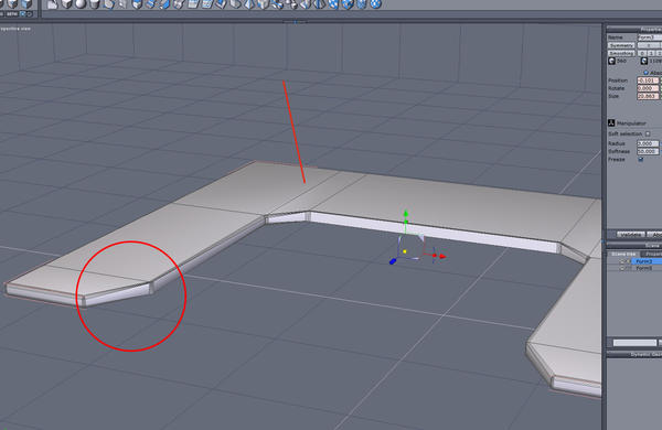
So, I am trying to make this shape with nice smoothed corners and a flat top.
In the first image, you see the shape I made simply by sweeping surfaces on a cube.
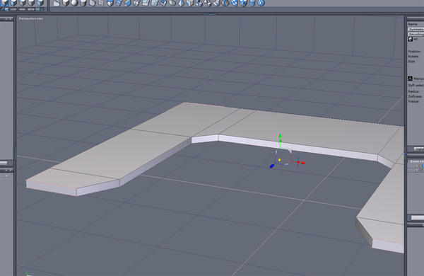
Of course, if I try to smooth it, it becomes something completely different, so here I have tried using chamfer.
what results, in the second image, is a serious problem. I don't know why it is happening or how I can remedy it.
As you see in the red circle, for no clear reason the lines seem to tighten up at the inner corner. Also, that inner corner is all busted and broken. The red line points to a fissure that has emerged on the top face at the line from which I swept.
I just want the original shape with nice smooth edges and a flat, smooth top but I clearly am going about it the wrong way.
Anyone able to help with this?
Daz 3D is part of 
Connect
DAZ Productions, Inc.
7533 S Center View Ct #4664
West Jordan, UT 84084
Licensing Agreement | Terms of Service | Privacy Policy | EULA
© 2026 Daz Productions Inc. All Rights Reserved.
Comments
From your top image it appears your model is OK. Do all the corners meet together nicely?....no misaligned edges?
In second image it looks like you selected vertical edges, and not bottom edges, instead of just the top surface edges, so when you applied a chamfer it went wonky.
Select only all the top surface edges, then chamfer, and all should be OK....you are on the right track. Repeat for the bottom surface as desired. Then do the vertical edges.
While you can select all edges and apply chamfer (it should work OK), sometimes it is better/easier/safer to do it in parts....as long as you make each chamfer edge the same size chamfer...otherwise it will be uneven and produce odd faces.
You can practice and learn starting with a cube as it has fewer selections needed and the results are more obvious.
I agree with DougS that you should not have chamfered the vertical edges. I tried modeling the way you have there, then chamfered only the edges needed to give a rounded look, but that also turned out to be a mess on the inside corners. Do you need to have those angled inner corners, or would rounded be OK?
If so, you could try a variation of the following.
1. Make a polyline with a right-degree angle, chamfer the inside corner
2. Copy/paste it and straighten out the chamfering to give a right-angle - line up the end points of the two polylines.
3. Use the ruled surfaces tool to join the two polylines, give it thickness, extrude the tip to form the angled end, delete the face where the two sections will join. Duplicate with symmerty and weld. Make sure the points are correctly welded.
4. Chamfer only along the highlighted edges
I tried the first suggestion, chamfering the top and bottom, rather than the vertical lines.
here's what happens.
I haven't messed with lines, like in the second suggestion, I will have to figure out quite how to do it yet -but It's still not the look Im going for. I want the angled sections, I just dont want pin-sharp lines.
Is the next pic more like what you are looking to do? See how I've changed the polyline to include the angled part.
To round off the edges of the pointy parts, select the edges, loop and use the "Extract edges around edges" tool (in the edge tools tab - looks like a cube with the edges shaved off)
Result - see A in the second pic. This will leave four N-gons in the adjoining faces. Fix by connecting the points to make an extra edge marked B in the pic.
In the meantime, I've figured out what the problem is doing it your way - it causes the face marked X in the pic to become an N-gon. This is easily fixed, but more work than the method I showed.
When you chamfer the edges, try doing it one loop at a time, making sure that the second chamfer doesn't overlap the first ;)
YES!
Ok, now to learn how to actually do all that lol. I have not worked with polylines even once.
The learning curve continues! Thank you!
OUCH.
Well, I made it as best I could for a first try, and it looks GREAT ...in Hexagon.
Pulled it into Daz studio to render and look what happened to the top. :(
:)
That looks very much like Studio's reaction to N-gons!
With the mesh selected in Hex, go to the top menu ->Selections -> Select over-4 points faces. If any faces are highlighted, you know you have the dreaded N-gon.
The easy, but messy, way to fix is to triangulate N-gons with Utilities ->Triangulate n-gons. A better method is to take a good look at the faces and see how you can make it all quads by cutting in new edges and/or connecting points. Both will work OK in Studio.
You will probably have to re-do the UV mapping.
Yes, it is well worth learning to do surfaces modelling - this is where Hex really shines!
Most of what I do starts with polylines :)
I bet it's an easy fix.
I'm pretty sure it has to do with the way you have your lines setup. the first thing I'd start with is selecting those lines on the top face and deleting them with backspace, then try chamfering. that will probably solve all your problems, and will restore your top face to one solid piece with no lines going through it.
here's an example I made rather easily, and quickly. very clean geometry. if you need those extra lines on your top face for something, you can always add them after you've chamfered. all I did was create the rough shape with a line tool, extruded the line with ctrl+ pull in direction you want with the translate manipulator, then close it off so it's solid, loop the outer edges then chamfer. you don't need to get the shape the same way I did though, since polylines aren't exactly precise.
I'm really kind of disappointed that people trying to offer help didn't know this, because it's pretty basic stuff.
another good order of operations if you're trying to smooth the corners also, is to ring the vertical lines and chamfer those first, then loop the horizontal edges and chamfer those. notice how the edges are rounded in the second image. if you try to do that in reverse order, you're going to end up with messy geometry every time, but the way I did it is as clean as it gets.
Hi user.operator :)
Don't know how much experience you have with Daz Studio - Just to check something, I made a replica of the method you suggested - see first pic.
The second pic shows what the render looks like in Daz Studio (same in Poser). The third pic shows what it looks like in Carrara, as well as in Bryce and Blender.
The simple fact of the matter is that not all applications are capable of handling N-gons. When giving advice, I don't know what render engine will be used, so always recommend using quads.
Must say, this is the first time I've ever come across someone suggesting that N-gon modeling makes for good geometry - it would certainly make life a lot simpler if all render engines could handle them :)
you can break the faces down into quads or tris. I've never really had a problem rendering them. in the second image, I assume that if you chamfer first then split the face with some lines (like in his first image) so they're however many sides you desire, you could remedy the issue. I don't use carrara or daz studio or blender, and bryce only once in a while.
I see what you mean though. here's a quick fix. select the top and bottom face, cut it from the model and paste it. then go up to utilities and select triangulate ngons. (4th option from the right, 2nd from the list). should render fine after that.
now there's a catch. if you for example, weld the 2 parts together, you'll end up seeing some of the disparities on the flat surface due to the lines. BUT if you go to edge tools and extract around in the stage of image 3, you can then follow the rest of the steps like before, and weld them, and those disparities will be gone and you won't see any sharp lines when rendering even when they're welded together.
So much easier to simply make it correctly in the first place :)
the point is, you really only need to triangulate ngons on planar faces in this scenario. I don't really see the difficulty in all of it. may take time to explain, but can be done rapidly if you know what you're doing. I'm pretty sure I've adequately solved the problems the OP's facing.
infact, triangulating the ngons on the non planar faces, adds about 500 more faces, with no noticeable difference when rendering.