An Iray Shader Mixer Cookbook
 mephoria
Posts: 120
mephoria
Posts: 120
In this thread, I plan to explore a bunch of different techniques for creating new Iray shaders within the Shader Mixer. I plan to run the gamut from basic (i.e. "the simplest possible shader") to intermediate (i.e. "multiple tilings and rotations within the same texture") to the advanced (i.e. "smearing input textures through noise functions"). In some respects, I hope to rectify the (current) lack of comprehensive documentation for the mixer as a whole and for specific Iray bricks, but I don't expect that I'll have the fortitude (or knowledge) to create anything comprehensive myself.
I welcome comments, questions, and (when I inevitably get things wrong) corrections. Hopefully, I'll be able to incorporate the results of such exchanges into a "master document" so that readers can have the most accurate possible information.
Daz 3D is part of 
Connect
DAZ Productions, Inc.
7533 S Center View Ct #4664
West Jordan, UT 84084
Licensing Agreement | Terms of Service | Privacy Policy | EULA
© 2026 Daz Productions Inc. All Rights Reserved.
Comments
<< This Page Intentionally Left Blank >>
Really simple shaders
The most basic possible Iray Shader Mixer (abbreviated ISM or SM in the future) shader will probably surprise you. Here’s how you can create it yourself.
Start by setting up a test scene. Create a primitive plane (World center; Z positive; 2M size; 1 division). Focus the camera on that plane. Set preview mode to NVIDIA Iray. (You’ll likely want to set up this preview in the Aux Viewport so that you can have it always visible while working in the SM.) Select the plane in the Surfaces tab so that you can apply new shaders to it.
Now open the Shader Mixer and create a new shader with File>New Shader in the SM menu. Use the mouse to select all of the bricks, and the X (i.e. Delete Selected Bricks) button at the bottom to delete them all. This is your complete shader -- apply it to the material with the Apply button. You’ll see the results of the shader almost immediately -- a uniform dull gray. Congratulations! You made a good start.
What do we learn from this? We learn that (pretty much) everything has a default value and that those default values aren’t too unreasonable.
Your second shader will be pretty much identical in effect to your first. Insert Bricks (Default)>Roots>MDL Surface from either the Brickyard or the (right-click) context menu. This is another complete shader and resembles the default from your previous one, so you can apply it and see that very little changes. (You might get a different shade of gray.)
This brick will give you a taste of input parameters, each of which is shown with a label (i.e. “Material”) and a connector circle that lets you link it to the output parameters of other bricks (if we had any others). The connector circle also gives you a one or two letter hint of the type of the parameter. In this case, MT is a material, C is a color, I is an integer, and F is a float.
Note that two of these parameters also have right arrows that you can click to view (and modify) inline defaults for the parameters. These are very handy, when available, because they mean that you don’t have to create new bricks or connections in order to change the defaults. (You still can connect to other bricks, and the provided values will override the inline defaults.)
You can also notice the Preview button, which does absolutely nothing useful for Iray shaders. Your best strategy is to forget that it even exists.
Our third shader will finally let us explicitly modify how the shader looks, and even let the end user tweak the behavior. First, insert a …>MDL>Materials>Simple>Simple Diffuse brick. (You’ll notice that I elided a few levels of the brick hierarchy. I’ll do that a lot since the names get pretty long.) Connect its output parameter to the Material input parameter of the MDL Surface brick by simply dragging the mouse cursor between the two circles. Then insert a …>Utility>User Parameters brick and connect the Color input of Simple Diffuse to the Auto Add output of User Parameters. True to its name, the output will magically add a new output parameter, and will automatically fill in its label, type, and parameter settings. Go ahead and set the value to a color of your choice, and apply the finished shader. You will see the color you chose, and you’ll be able to change the color in the Surfaces tab.
You can easily change the value, but you can also edit the settings to change other aspects such as the user parameter label (which isn’t the same as the SM parameter label), and Name. The name is what is used internally to identify the parameter. In particular, if it’s the same as a parameter name in an old shader, the value will be carried over when you load this shader “on top of” the old one. Every parameter name should be unique within the shader.
Future sections will add in additional concepts to yield ever more complicated shaders, but for now you are on the path to being able to create nifty shader effects.
Preview Blues (and pinks) -- fixing OpenGL previews
The simple shaders described earlier will look great (or at least acceptably blah) in Iray renders and Iray previews but they, like many ISM shaders, will do funny things when you use Texture Shaded OpenGL previews. Typically, they’ll be grayish instead of picking up your desired colors, and then they’ll randomly change to garish blue or pink colors when you highlight them or manipulate them. This is because the preview renderer picks up values from specific magic names within the shader parameters. In order to fix the shader to show your chosen color in the preview, edit the parameter name (not the labels) to be “Diffuse Color”. (In order to change the parameter name, you can go to the User Parameters brick, use the expansion arrow if necessary to show the value of the parameter, and then edit the parameter settings by double-clicking on the name [if no gear icon is shown] or clicking on the gear icon if it is shown and choosing Parameter Settings from the menu. You'll get a new dialog with lots of fields, but the very first of them is the Name field, which is what you'll want to change. You can also find the same gear icon beside the parameters in the Properties tab located beside the Brickyard tab.)
In order to fix the flashing blues and pinks, add a user parameter (via the menu in the User Parameters brick) and set it to Property Type: Color; Name: Ambient Color; Label: Ambient Color; and Hidden: yes. (It doesn’t need to be hidden, but this’ll avoid confusing your customers.) You can leave the color as the default black.
You should also be careful about using parameters named “Horizontal Tiles”, “Vertical Tiles”, “Horizontal Offset”, and “Vertical Offset”, as the preview renderer will apply the values to any Diffuse Color texture maps, whether you want them to or not, and no matter how they are actually used in your shader.
Beyond Tiling -- Fun with Texture Coordinate Info
We’re all used to using images as texture maps. Typically this involves carefully matching the image up with a UV map which tells where on the surface to apply the textures. In the most common process, the model creator uses specialized tools to create a UV map, which provides an arbitrary discontinuous mapping from 3D surface points to 2D points in the texture map. All of the points in a UV map into the range 0.0..1.0 along both the U and V axes. In this case, we don’t need to worry about what happens when you look up coordinates below zero or above one. We just make sure that the surface zones match up with the template and let the UV map handle the rest.
However, for some models, the UV map is continuous enough that we can apply arbitrary pattern textures. Garments, landscapes, walls, and such all benefit from not only applying generally pattern textures but tiling them. This is accomplished internally by simply modifying the coordinate system so that we map surface points to a different range. Texture maps simply wrap around from 1.0 straight back to 0.0 (via modular arithmetic), which means that if we (for example) remap our UV coordinates to run from 0.0 to 5.0 we will wrap around multiple times, and end up tiling the image 5 times. The standard Texture Tiler brick accomplishes this by taking the current UV coordinate and multiplying it by the provided tiling factor (after first adding the provided offsets). The results are wrapped up in a Texture Coordinate Info (TCI) structure which supplements the transformed coordinate with potentially transformed versions of the U and V Tangents. (We can mostly ignore the tangents since they mostly only affect normal maps in rotated coordinates.)
Because the Texture Coordinate Info is mostly just a transformed coordinate, we can use it for things other than simple linear tiling. Instead of fixed scaling, we could use exponential or logarithmic scaling, and instead of fixed translation, we can randomly perturb textures via noise functions. And, of course, we can perform arbitrary rotations.
Noise-based perturbation -- sometimes called turbulence or warping -- turns out to be surprisingly easy. We create a set of bricks which takes the coordinate from a TCI input, adds a per-point translation vector, and wraps it back into a new TCI. The translation vector can come from any noise bump texture.
When we combine these into a custom Coordinate Translation brick, we end up with two inputs: the translation vector, which we’ll hook up to our bump noise brick, and an input TCI, which we can take from a Texture Tiler brick or from a ..>MDL>Default Modules>base>Coordinate Source brick. (This is one of the few cases in which there’s not a useful default value, so we have to provide an explicit TCI value.) A full shader, including tiling, would look like this:
and produce results like these. (Note that the attached shader uses a different image, which will hopefully be present in your library.)
It's perfect for breaking up the dull perfection of a cloth weave or a brick wall. Notice that even though the input image repeats due to the tiler, the noise is simply scaled with no repetition.
Call the Exterminator -- Bricks with Bugs
Because the Shader Mixer is one of the least used facilities in Daz Studio, there are fewer people testing, even fewer reporting bugs, and (presumably) lower priority for fixing bugs when they are found. Thus it appears that a few misbehaviors have slipped through the cracks and are lurking in the darkness waiting to ambush unwary shader builders. These are the ones that I have discovered thus far:
Blend Colors -- the version of Blend Colors located under ..>Default Modules>base doesn't work -- it always returns white, no matter the inputs. However, ..>MDL>Procedural Textures>Blend Colors promises exactly the same capabilities and does work. Using it may well be easier than the workaround I originally suggested. (Original report: the …>MDL>Default Modules>base>Blend Colors bricks would seem to be the ideal facility for (logically enough) blending colors. It offers a wide variety of mixing modes including weighted averaging, burning, etc. Unfortunately, it appears that whatever parameters you use it returns a uniform white. For the most common variety of blending -- weighted averaging -- you are best off using the (intuitively named) ...>Default Modules>math>Lerp brick. The name stands for linear interpolation, which is exactly the same as a weighted average. You will need to remember to set the Operation setting to color,color,float so that it knows how to interpret the inputs.)
Texture Tiler -- the Texture Tiler brick is used in almost every shader, and almost every part of it works. However, if you show advanced parameters you will see a Texture Coordinate Info input, which would be incredibly handy for chaining coordinate transformations if it worked. Unfortunately, any supplied value appears to be totally ignored. The best workaround is to either include the tiler first in your transform chains, or just build a better tiler -- which I’ll do in a follow-on post.
Custom bricks -- the Shader mixer will allow you to save arbitrary grouped bricks as Custom Bricks . This should be great, except that I have never once succeeded in loading one of these bricks. The custom bricks list in the Brickyard ends up only showing saved versions of standard bricks, which doesn't seem to be particularly useful or custom. (I do, actually, use the list to provide quick access to my favorite "standard" bricks, but that still isn't nearly as useful as keeping a library of bespoke utility bricks.)
Thanks for this! No kidding the Shader Mixer is "one of the least used features in DS"--at least in my house it is--but this gives me hope of someday comprehending & actually using it.
I secod what Blind Owl said. Your work on this tutorial is much MUCH appreciated.
Now I just need to understand it ;)
My Goosebumps have Goosebumps -- combining bump/normal maps
The handling of bump maps in Iray is a little bit odd, and this makes many operations confusing. The most commonly requested -- combining multiple bump maps -- was already confusing, but the Shader Mixer makes it even more confusing by “faking it”. The final conclusion, however, is that Iray and the Shader Mixer have support for having two bump maps “at a time”. It’s easy to provide those two, and very hard to add a third. If you want to skip all the complicated explanations, just remember that Uber Add Geometry can handle two bump maps (from any source) and that anything that looks like it could add a third probably won’t work.
First, let’s explain what a “bump map” is. Internally it is represented as a surface normal with a value at every point on the surface. This is a unit vector -- basically, an arrow whose length doesn’t matter -- which indicates what direction we should pretend the surface is facing when we calculate how light bounces off the surface. It is combined with the geometric normal -- which is the direction the surface is really facing, and the resulting adjusted normal is used for reflection calculations and gives the illusion that the surface is curved more than it really is. The big advantage of this is that it applies to every point on the surface, even those without vertices so that you don’t need a high-resolution model. The disadvantage is that the illusion breaks down quickly when you aren’t viewing the object straight on. You also can’t easily combine them. When one source says “slant left and up”, and the other says “slant right and up”, it will average out to “point straight up”, but that won’t necessarily look right to the viewer. Therefore, there’s some question whether you ever actually want to combine them at all. However, if the different maps have bumps in different places, or if they are at substantially different scales, then things don’t glitch too badly and you can have a result that’s worth using.
You will see bump maps in two different formats. A normal map directly encodes the unit normal vector by using the RGB channels of a color to represent the XYZ components of the vector. It looks like confusing op-art to human viewers, but it’s very easy for the shader to read. A height map (which is also, confusingly, simply called a bump map) shows the (pretend) height of the bump at each point on the surface. This can’t be used directly during the render, but can be turned into a normal map before the render starts, by comparing the height values at neighboring pixels and figuring out the slope between those points. Either way, you end up with unit normal vectors that can be used by the renderer. You can load normal maps through the ..>Functions>Geometric>Texture Instance Normal Map brick, and height maps through the …>Texture Instance Bump Map brick. Both of these bricks include scale factors which control how tall the bumps pretend to be, but they have different ranges of useful values. Texture maps seldom look good with values higher than 1.0 and often look good around 0.15. Height maps usually like values of at least 1.0 and can go as high as 10-30. (You would hope that the ..>Bump or Normal Map brick would somehow reconcile this but it doesn’t, and thus ends up simply being confusing. That’s why I don’t recommend you use it.)
You can also create procedural normal maps from various noise functions, including Perlin, Flow, Worley, and Flake. Rather than make you try to figure out how to adapt standard surface noise into a normal, Iray provides various Noise Bump Texture bricks. Most of them are under ..>Default Modules>base, but there are a few DAZ-provided variants under …>Procedural Textures. I prefer the first set, but your mileage may vary. All of the Noise Bump Texture bricks have almost exactly the same parameters as the corresponding Noise Texture bricks and can be used in parallel.
Typically you will add a global bump map which will have exactly the same effect on every layer in your shader. Iray accomplishes this by applying the changes to the normal vectors at the very beginning of the render (but after applying displacement) and using them through the rest of the render process. In spite of this, the bricks which apply the global bump are generally added at the end of the chain, after all other effects are specified. This can be done through the native Iray brick ..>MDL>Material Editors>Add Global Bump or the DAZ-created …>MDL>Material Editors>Uber Add Geometry. In both cases, the bricks should be named replace rather than add -- they will overwrite whatever global bumps you had before.
The Uber Add Geometry brick goes beyond the global bump map by having two parameters: Base Bump appears to set/replace the global bump, while Second Bump appears to cheat by co-opting and overriding a mechanism designed to provide “per-layer” bump maps. Using two bumps is easy: just put one in the Base Bump parameter of Uber Add Geometry and one in the Second Bump parameter. Done! This is what the standard Iray Uber shader does with the paired “bump” and “normal” inputs, but you can just as easily combine two height maps, or a height map and a noise bump texture.
As you can see from the output shown here, it combines a vertical bar taken from a provided height map with random bump noise provided by a fractal flow noise bump texture, with the random noise going around and over the static bar. I've also attached a copy of the shader, though you'll have to provide your own static height map.
Stop here if you aren’t ready for a highly speculative, highly technical explanation.
Still reading but this is a great start...fantastic job Mephoria! Nice to see someone taking on this task.
Two things:
First I highly recommend (if your not already doing this) that you keep a copy of this somewhere as well as here. I still miss the info we lost from the global illuminations thread when Shadermixer was first introduced. It disappeared when the forums changed over as did many other threads.
Second, I noticed in your fourth post Preview Blues (and pinks) -- fixing OpenGL previews that you discuss renaming the bricks. Now I'm pretty sure I remember how to do this but for many people who haven't played with shadermixer previously they would need more info on how to do this, maybe including screenshots.
I'm really excited about this thread and I'm so glad that you've taken this on. I hope you don't mind feedback...if it's a problem let me know and I'll stop : )...also if you need anyone to read through and proof read I'm happy to test the instructions...I have fond memories of doing this for Zigraphix when she was working on her tutorials.
Thank you for the feedback, @Pendraia. I always appreciate comment, suggestions, and corrections.
I am indeed keeping it in a separate (though currently disorganized) document. Once I get it more organized, I'll probably post a link to the living document to supplement the "ongoing thread" format. However, the reminder is a good one.
I've added the information in a textual form. I'll look into creating corresponding screenshots, though you may have noticed that I'm better with verbose text than informative graphics.
Again, I really appreciate the feedback and will certainly be glad if you contribute more. I might or might not take you up on the offer of pre-testing -- not because it won't be useful, but because I tend to get "caught up in the moment" when I'm writing and want to share it immediately. I'm always happy to adjust things (or even heavily edit them) "after the fact", though, so feel free to make suggestions -- either here or via private messaging.
All good...I like your explanations as they are really informative and help someone(me) who doesn't understand the maths behind shaders all that well to understand it better.
A living document sounds wonderful as it can be updated as no date DS will continue to update also.
If I get chance I'll try and put the basics of renaming with screenshots if you don't object...not sure if I'll run out of time though as I only have one more week of holidays left and I work full time...
<< Long duplicate post removed. >>
The Ins and Outs of Displacement
Displacement mapping is often considered alongside bump mapping because it serves a somewhat similar purpose: adding surface curvature (and sometimes other details) to a low-resolution object. In fact, they are quite different under the hood. Bump mapping is a very low-cost way to provide the illusion of detail, while displacement mapping is a relatively high-cost way to provide true geometric detail.
Displacement mapping is actually pretty much identical to morphing: it specifies a direction and a distance in which to move each vertex on the model’s surface. There are, however, a few things that make it different from a typical morph:
The map can be created by a 2D graphics tool rather than a 3D modeling tool.
The points typically only move in and out from the surface along the surface normal.
It can be applied to newly created vertices after dynamic subdivision.
I believe that it is the last property that makes displacement mapping both popular and dangerously expensive. Each subdivision increases the complexity of the model exponentially, which means that they can end up consuming large amounts of memory (and possibly computation time.) Whereas you can use maps to create smooth curvature with a relatively small number of subdivisions, users and creators always seem to want to use it to create sharp discontinuities, which require quite substantial numbers of subdivisions. Unless the software is very clever, the complexity of the subdivided model will always be higher than if the discontinuities were designed into the model geometry from the start. Conventional wisdom holds that Iray is not particularly clever in this respect.
My advice, which is probably not typical, is to think twice before using any displacement that requires you to set the SubD Displacement Level above 0. If the amount of subdivision required for smoothing the surface in the Render Subdivision Level (under Parameters>Mesh Resolution) isn’t enough, you are probably expecting too much from your displacement map, and you should instead look for (or create) a more detailed object model. However, you will find that some commercial products will set the SubD Displacement Level all the way to 12, which (I believe) will increase the complexity of the model 16,000,000 times. (That’s 4^12 multiplied by the original complexity of the model, and it will make your graphics card cry.)
Displacement lengths and heights are expressed in real-world units -- specifically centimeters. (They are, however, apparently multiplied by the object’s Scale parameters. I don’t know exactly where and how this scaling is applied.) In addition to actually providing displacement vectors scaled to your desired distances, you will need to specify a global Displace Max setting in your MDL Surface brick. This is simply the greatest vector length it will accept, regardless of the direction of the vector. (Longer vectors will be truncated to this value, producing unexpectedly flat surfaces.) As an example, if you know that your height values will vary from -9 meters to 1 meter, you would specify a Displace Max value of 900. I’m not aware of any specific penalty for specifying a value that is larger than needed, but I imagine that it will slow things down by increasing the scope of bounding box calculations.
Unlike with bump maps, the trivial conversion from heights to displacement values allow us to treat height maps as “native” formats can use height maps as a “native” format, and this is what is done in the Iray Uber shader. The …>Geometric>Special>Texture Instance Displacement brick does the actual work, by mapping the texture maps’ height values (which are in the range of 0..1) to a minimum and maximum displacement value and providing a value for the Displace Max setting based on these limits.
You aren’t limited, however, to the built-in support for displacement texture maps. By doing the conversion described above, you can take the output of any noise function (or arbitrary floating point function), and convert it to appropriate vectors. If your height values have not yet been scaled from the standard 0..1 output range, you’ll likely want to use a second Multiply brick to rescale to the desired height in centimeters, maybe preceded by an Add brick to shift it to a -0.5..0.5 range. (You could also use the ..>MDL>Default Modules>math>Lerp brick to do the scaling in one step. I’ll discuss this incredibly useful brick more in another section.) Note that you will need to explicitly provide a value for the Displace Max, but typically that will be exactly the same as your multiplier.
Once you have your displacement vectors, you will typically apply them to your model via the Uber Add Geometry brick. (The same one that’s used for bump maps.) As with bump maps, this brick often appears at the end of your Shader Mixer graph but is always actually applied first -- before the global bump map is applied, and before the render properly begins.
You’ve probably noticed that I haven’t addressed the possibility of directly using displacement vectors that are not parallel to the surface normal. This is intentional. Arbitrary vector displacement is very powerful, but it’s also harder to specify and implement useful values. I hope to investigate this more in a later post, but it’s definitely beyond the scope of this one.
You could make a regular Iray-Bricks cookbook out of all this, and sell it in the store, probably. Nice work.
In Space, No One Can See Your Seams -- Fun with Coordinate Systems
In order to justify this section, we’ll start with a render of four primitive objects and the shader which was used for the render. The scene consists of four 2 cm objects: a sphere, a cylinder, and two planes. The planes have, however, been rescaled in the X-axis and rotated around their Z-axes. The seams in the UV Maps are painfully visible, as is the stretching of the scaled objects, and the fact that the “random” noise is identical in the two planes.
The shader has a few interesting elements. It has a Choose Value brick which allows us to switch from the Perlin Noise Texture shown in the render to a Checker Texture (which we’ll use later) by simply changing a boolean parameter. It uses a Rescale Coordinates custom brick which simply multiplies the input coordinates to achieve tiling behavior but (unlike the standard Texture Tiler) accepts and respects an input Texture Coordinate Info. And, most interestingly, it includes the …>MDL>Default Modules>base>Coordinate Source brick. By changing the Texture Coordinate System enum that it takes as an input parameter, we can change all the (potentially negative) behaviors described in the first paragraph.
The seams appear because of the limitations of the default UV Coordinate Space, which maps every point on the object’s surface to a 1 unit square, with 0.0 denoting the bottom and left boundaries, and 1.0 denoting the top and right. You can trivially map a square plane to this space (though the exact details will depend upon the number and placement if internal vertices). However, as every mapmaker might tell you, there is no good way to evenly map all points of a globe to a flat plane and, like the cylinder, there will always be a point at which it “wraps around” and creates a seam. In some cases, you can hide the seam in a spot that is covered or pointed away from the camera, but they’ll still exist for solid objects and always present a potential problem.
You can eliminate seams by eliminating the mapping to a two-dimensional space, and working in a more physically-based XYZ Coordinate Space. (This could also simply be called “space”.) In these spaces -- Iray provides two of them -- X represents “left to right”, Z represents “forward and back”, and Y represents “up and down”. (You should be careful here. Other 3D programs, and your math textbook, may swap the meanings of Y and Z. DAZ Studio, however, is consistent in its usage.)
We’ll start with the World Coordinate Space (specified by the enum value texture_coordinate_world). In this space, all coordinates are specified by the distance from the scene origin, measured in centimeters. Since texture maps are mapped to the 0..1 range, they will be considered to be 1-centimeter square and will be tiled to cover surfaces of any size. Procedural textures will also consider 1 centimeter to be the “unit size” and thus, for example, an unscaled (single level) Perlin noise will have 1 “dot” per centimeter.
When we change the Coordinate System parameter to texture_coordinate_world, we see that all of our seams disappear, and none of the textures appear stretched. The two planes don’t repeat textures and, instead, the pattern smoothly flows across the gap to form a single clean pattern. Because Perlin noise is smoothly continuous in 3 (or more) dimensions, you could orbit all the way around the sphere or cylinder and still see no discontinuities. Be aware that not all noise functions operate in three dimensions. For example, Flow Noise Texture, though often superior to Perlin Noise Texture, is two-dimensional and will thus simply produce straight lines in the Z dimension of solid objects.
A potential disadvantage of the world coordinate system is that the patterns will stay in the same places in space even when the objects move. This can be fine in static images but can be very disconcerting in an animation. It also becomes difficult to align repeating patterns to specific boundaries, as illustrated in this checkerboard image. The checkers are set to do one color alternation per unit, so the 2cm objects should have exactly two pattern repetitions. While this is true for the cylinder, the fact that the repeats don’t align to the bottom produces an ugly result. The proportions are correct for the rotated plane, but we might prefer for the pattern to rotate along with the plane so that the straight lines of the checkerboard are parallel to the straight lines of the planes. (We could accomplish this by adding a rotation parameter to the texture tiler, but it wouldn’t adapt if the object rotated over the course of an animation. Likewise, we’d end up with different coverage if the planes were rescaled.)
For situations like these, we might wish to resort to the Object Coordinate System (specified by the enum value texture_coordinate_object). This system still uses XYZ coordinates, and still has a 1cm base scale. However, the “origin” of the coordinates is changed to the object’s origin. (This varies with the object but is usually either the exact center or the bottom-center. You can see observe its location if you enable the transformation widget via the Universal Tool.) The base scale is also multiplied by the Scale parameters of the object, and the coordinates are rotated along with the Rotation parameters of the object. The net result is that the same points on the object will have the same coordinates no matter how you transform it. This allows your animations to have the expected results, and to rescale objects without having to rescale your textures. It means (for better or worse) that two instances of the same object will have identical textures (just as they would in UV space). You can clearly see the difference in the Object coords render, which keeps all other parameters unchanged from the World coords render.
The edges of the squares are aligned with the edges of the cylinder and planes, and the squares are scaled and rotated to match the transformations of the planes. (Since the base dimensions of the planes are still 2x2cm, there are exactly the expected 2 pattern repeats in each dimension.)
Object deformations (as provided by morphs, deformers, and displacement) are not scaled or corrected in object space. These all make real changes to the geometry, and the shader’s measurements are made based on that new geometry. Since many DAZ character movements are based upon morphs, you should not count upon object space shader operations “staying put” after these transformations. (In contrast, the mapping from object vertices to UV coordinates do stay constant under these sorts of transformations, which is why you can count on Vicky’s lipstick to stay in place when she smiles.)
Covering the surface -- varying vs. uniform vs. direct compute parameters
In general, single values aren’t useful for shaders. We don’t want to know the color of a surface; we want to know the color at every point on the surface, and we want it to be continuous so that we don’t see pixelated values if we zoom in really close. The shader mixer handles this by dividing values between uniform, direct compute, and varying parameters.
Uniform parameters are what we typically think of as values. They are the same -- thus the term “uniform” -- no matter what part of the surface you are considering. Examples are constant scaling factors or the Refraction Index parameter. Uniform parameters are indicated within a brick by adding the string “ | U” to the parameter names.
Direct compute parameters are like uniform parameters, but even more restricted. Their values are constants or simple calculations which are performed by DAZ Studio before invoking Iray. Examples include SubD Displacement Level and Texture Tiler parameters. Direct compute parameters are indicated within a brick by adding the string “| D” to the parameter names. Warning: The Shader Mixer sometimes mislabels direct compute values as uniform, which can make it hard to recognize the restrictions. In the attached figure the Displace Max input can only be connected to the corresponding user parameter because it was in fact provided directly. You would not be able to attach it to the output of a Choose Value brick, for example.
Varying parameters are actually “continuously valued functions”. The value you get depends upon the position on the surface you are currently considering. It’s easy to think of them as an array of values like the pixels in a texture image, but this isn’t accurate. We may need the value of an image map at any arbitrary point on the surface, even “between pixels”, and the varying texture values will be computed on the fly by interpolating between multiple pixels in the image. Any output parameter computed from varying inputs will itself be varying. Because most of the parameters passed through the mixer are varying, they are not explicitly labeled.
Input parameters specified as direct compute can only accept direct compute values, while parameters specified as uniform can take either direct compute or uniform values. Varying parameters can take any of the three sorts of values, and often do end up receiving simple uniform values. For example, we choose a single specular color or a fixed weight between layers. This is entirely valid and simply makes the associated function trivial to evaluate. The value of the “0.5” floating point function is simply “0.5”, whether evaluated at UV coordinate (0.1, 0.9) or spatial coordinate (5000, 0, 3). However, the same parameter could be supplied with a tiled image map or a purely procedural noise function, and the shader would still function.
In the editor which allows you to define brand new parameters in the “User Parameters” brick, you can choose whether the user has the option to define a fixed value, and image map, or both. This is controlled via the “mappable” and “require map”. “Mappable” parameters are varying, while unmappable parameters are uniform.
My (Displaced) Goosebumps have Goosebumps -- Combining Displacements
Compared with the difficulty of combining bump maps, displacement maps are refreshingly easy. To combine two displacement vectors, you merely add them together. You may need to adjust the Displace Max parameter to reflect a combined maximum but this, too, can be handled by simple addition. Alternatively, you could combine two displacements via weighted averaging using the Lerp brick, and the Displace Max would be the weighted average of the two individual maxima. If the two displacements are expressed in terms of height maps, you can perform the addition before or after multiplying by the normals, which provides excellent flexibility.
Unfortunately, you will have more trouble creating non-height-based components, because these typically involve multiplying by tangent vectors, which appear to have undefined values during the displacement computation phase. All my attempts to access tangent information during displacement calculations [whether directly through …>Default Modules>state bricks or indirectly through Bump Noise Texture bricks] have resulted in zero values, invalid values, or program crashes.) You can compute them manually, but the process is highly complex and technical.
As an experiment, I used a plane with known tangent values and supplemented a height-based noise displacement with a small displacement in a random (noise-based) direction on the tangent plane. The result is shown here, and I’ve attached the scene which generated it. While interesting, it requires a highly-subdivided model, and (due to the missing tangent information) can’t easily be generalized to any object other than a plane. Update: You can achieve somewhat similar effects by simply perturbing the height displacement in a small totally random direction. This will produce results similar to those illustrated but will generalize to any model. I'd still consider this to be only suitable for distant features, as it looks quite unrealistic when viewed closely.
What we want, In many cases, is to apply an additional height-map displacement to the result of a prior displacement to achieve surface roughness and, potentially overhangs. This is difficult (if not impossible) to perform within a shader, because all displacements are performed at once, and the second displacement has no access to the modified normals from the first one. We can, however, use some workarounds to achieve similar effects. Displacement-like effects can come from three mechanisms which are all applied sequentially, allowing the latter mechanisms to enhance prior results:
Morphs: As noted earlier, morphs are functionally identical to displacements, but are specified in different ways. If you are creating a new model, or have the tools to add morphs to existing models, you can use those for features that don’t require subdivision.
Displacement: This has all the strengths and weaknesses we’ve already discussed. In particular, you can use it with procedural noise, but it may require subdivision to get the desired effects.
Bump Maps: The will not affect shadowing or the “profile” of the object, but it’s perfect for applying small details without subdivision, and can provide the illusion of overhangs. Bump maps are also the only displacement-like mechanism which can operate in world coordinate space, thus allowing multiple instances of the same object to have the appearance of different geometries.
How Not to Build a Light Bulb -- What Doesn’t Work, and Why
When you try to do clever things that push the system to its limits, you sometimes experience failures -- things that seem perfectly logical sometimes simply don’t work. By mapping out these “failure zones”, we can reduce confusion and avoid wasting time. We can also periodically revisit these failures when new software versions are released, and see whether new techniques have become available.
Tangent vectors during displacement calculation: Displacements are computed during a pre-phase before rendering actually begins. During this phase, the …>Default Modules>state>Texture Tangent U/V don't seem to produce meaningful values, and thus can’t be used to generate non-height-based displacement.
Bump noise textures during displacement calculation: This is likely a consequence of the previous point. The various Bump Noise Texture bricks appear to produce invalid (i.e. NotANumber) values when invoked during the displacement phase.
Displacement computations in World Coordinate space: During the displacement phase, attempts to use world coordinates end up operating in the object coordinate space instead. This is unfortunate since it makes it harder to achieve useful effects with terrain tiles or instanced objects. However, when you consider how costly it would be to apply per-instant displacements, the limitation does make sense.
Volumetric clouds: The …>MDL>Material Editors>Uber Add Volume bricks accepts several parameters which are varying values. In theory, we might use this to make the volumetric properties (i.e. scattering and absorption) vary with the spatial coordinates, which would allow us to make clouds with varying density. In practice, when we apply varying inputs to these parameters, we get uniform zero values. We must use uniform values for all volumetric parameters if we wish to get useful results.
Working for Scale -- Lerp and SmoothStep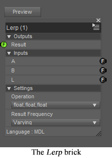
Much of the time, it’s easy to feed the output of one brick as an input to the next, simply because many bricks deal in values between 0 and 1 (aka the unit range). However, there are other situations in which you need to rescale values, like converting noise outputs to displacements, or converting the -1..1 output of the Sin function to the unit range. There are also situations in which you need to clamp values -- typically mapping all values below some threshold to 0 and values above a higher threshold to 1. These sorts of operations are easily handled by combining two bricks: ..>MDL>Default Modules>math>Lerp and ..>MDL>Default Modules>math>SmoothStep.
Lerp -- which stands for linear Interpolation -- takes an input L (typically in the unit range) and produces a new value between A (for a value of 0) and B (for a value of 1) with other input values interpolated via a weighted average. (The precise formula is “(B-A) * L + A*). For example, if the values were A=2, B=4, L=0.25, then the result would be 1 quarter of the way between 2 and 4, or 2.5. This, effectively allows you to convert values from the unit range to any other range you like.
By default, Lerp operates on floating point inputs, as described above. However, it can also be used to interpolate between colors or vectors, thus supporting color blending and combined displacements.
The SmoothStep brick is essentially the opposite of Lerp. It accepts values from some arbitrary (known) range, and scales it to the unit range. The formula for value L within a specified range A..B is “(L - A) / (B - A)”. Thus, for A=2, B=4, L=2.5, the result would be 0.25, (exactly reversing the Lerp example above). Inputs below A are clamped to 0 while inputs above B are clamped to 1. It is common to use SmoothStep to expand a portion of the values from a noise function into the unit range while clamping all other values. For example, if A=0.75, B=1.0, and L is the output of a noise function, the lowest three-quarters of the noise output would be forced to 0, while the remaining quarter of the output would be remapped to the unit range.
Note that all the inputs to these bricks may be varying or uniform. Often the L parameter of Lerp is a user-provided uniform weight with the other values being varying image maps. In other cases, the L parameter can be the output of a noise function while A and B are uniform numeric bounds or colors. One popular application (which I will cover later in more depth) involves using Lerp to combine the varying outputs of two noise function via the varying output of a third noise function to produce four-color noise.
By connecting the output of SmoothStep to the L input of Lerp, you can create an arbitrary Rescale function, as shown here. This would make a very useful custom brick, once the DAZ crew fixes the bug which keeps such bricks from loading.
I'm bookmarking this.
This whole texture thing is so excessively complicated it's actually comical. I've seen ultra-professional texture apps that were easier to comprehend than this. What they need to do is hire someone that can simplify all this by orders of magnitude. Seriously.
The complexity is - at least for the most part - the result of the MDL specification, which Daz doesn't control. In any event simplifying would limit what it could do.
Do you mean that Daz is not even allowed to tweak and re-word the user interface to make it easier to use? I thought DazStudio, unlike Bryce, was a truly 100% Daz owned product. In any case, if we allow progress and innovation to be suppressed in any way, it's gonna be a sad future.
Connecting the Blots -- Four-Color Noise
Most of the Texture Noise bricks give you the ability to blend two colors in a pattern controlled by the noise function. If we choose Perlin Texture Noise with pure red and blue as our input colors, we will get a pattern with various shades of purple. Because every point is part of a smooth gradient between 0 and 1, we will get almost no pure reds or blues -- just purplish in-between shades. However, by using the Noise Threshold parameters, we can clamp high and low values to 0 and 1, with smooth gradations between the middle values. This will give us larger areas of pure color, with smoothly blended zones between them. (For noise textures without built-in clamping, we can use external SmoothStep bricks to clamp the Result Mono and then use Lerp to do the color blending. This requires more bricks, but the effect is identical.)
For the renders shown here, I used the Coordinate Source brick to specify object coordinate space, which allows the entire garment to have a seamless texture -- such as would occur with tie-dye-like techniques that tint the garment after it has been constructed. Because this space uses real-world coordinates in centimeters, I specified a feature Size of 15 (i.e., roughly 6 inches). I specified Noise Levels of 6 just because I liked the way it looked. Warning: Not all noise functions operate in 3 dimensions, and may merely produce streaky effects in the z-direction. Perlin and Worley noise can both work in 3 (or more dimensions), but Flow noise is restricted to two -- and is, therefore, better suited for UV coordinate space.
For a much more interesting effect, we can feed the results of two separate 2-color shaders into a third shader which blends their color outputs into a combined 4-color shader. All of the same sorts of parameters apply, but we need more of them: we need a total of 4 colors, of course, but we will benefit from providing separate Size, Noise Levels, and Noise Threshold parameters for each of the three noise functions. (In some cases, identical values will suffice, but we can produce a broader range of effects by allowing per-brick controls.) Even more importantly, we will wish to make sure that the third mixer brick has a different Phase value. (The phase provides movement along a 4th dimension which has the effect of producing different patterns for the same coordinates. I would recommend using phase values that differ by more than the feature Size.) If we use identical Phase values, then all of the noise functions will produce identical values, which will prevent certain blending combinations from ever occurring. We could also provide independence between the noise functions by using different feature sizes (or even wholly different noise bricks), but the phase parameter is still the easiest solution.
The complete 4-color shader is shown below. The renders use pure red, blue, green, and white with a variety of threshold and phase values. I find that the results are slightly prettier if you use identical phase values for the color noises and a different value for the mixer noise, but your experiences might differ. You can get other nice effects by using a SizeMix value that’s lower than the Size1/2 values, or by using identical (or similar) values in two different color channels.
Four-color noise is used most often -- with far more subtle color combinations -- for rock and soil terrain textures. However, I think that it produces some excellent garments that I’d love to find for sale at my local t-shirt store.
I have attached two different complete shaders to this post. "basic-four-color.duf" is the exact shader shown above, while "uber-four-color.duf" adds the core four-color implementation to the "Diffuse Overly" channel of the standard "new material", thus allowing tiling, bump maps, glossiness, and image maps for all of the standard parameters. You should be able to apply this over many existing shaders to add a splash of color to your scenes. (You can adjust the Four-Color Overlay Weight parameter to make the colors more or less prominent.)
@Nimos: I actually don't think that the basic shader system is unreasonably complicated. If you look at the Really Simple Shaders post, you'll see that a single color diffuse requires 3 bricks to define, and only has a single parameter that users need to deal with. If you ignore the standard endpoints, you have one brick, one parameter, one color -- it's that simple. If you want to add glossiness, you can still use just one non-trivial brick -- this time Simple Plastic -- and connect 2 or 3 parameters. (You really only need Color and Roughness for most glossy materials. The Ior parameter controls reflectivity more than glossiness, and the default value works great.) If you want bumps, you need one more brick, since you need to define an actual pattern for the bumps. There's a Texture Instance Bump Map brick that'll suit your needs 90% of the time. (The rest of the time, you might want to get fancy and use a noise brick instead. That'll require more parameters because there are lots of ways to modify noise.) You may need a tiling brick as well, but only if you actually need to tile your bumps. It continues from there, with each new capability requiring one or two more bricks and varying numbers of parameters depending on how much customization you want to support. This is why I'm able to show complete, usable shaders -- some of them quite advanced -- in each post using fairly small screenshots.
The reason that the standard uber shaders (or even the "new material" material) seem so complicated is that they are trying to allow extreme customization without requiring you to use the shader mixer at all. Most of the apparent complexity is simply in making sure that every parameter accepts an image map, and that all of those maps use the same tiling. If you didn't want image maps or tiling, you could get all of the capabilities of the uber shader with 3-5 bricks and only as many parameters as you actually planned to use. Alas, simple shaders don't sell products, so the average merchant really wants the ability to go in and provide velvety sheens, dual-lobe reflections, subsurface scattering, etc. The complexity of the uber shader allows him to get all of that without wading into the shader mixer at all. The cost is that it appears to be really complicated, even though you can achieve adequate effects with just diffuse color, glossy roughness, and bump maps (plus possibly tiling). That's 6 bricks and 5 parameters.
On the other hand, there are certainly things that could make life simpler. For the shader mixer, simply adding a way to find bricks combined with usable interactive documentation would lower the learning curve and make things easier for experienced users. The ability to save and load grouped bricks would be wonderful, especially if combined with a way to hide unneeded parameters to those grouped bricks. Being able to set parameter values "in-line" rather than requiring separate Direct Value bricks would make shader graphs much more readable. For folks working with the existing shaders, a simple way to condense shaders to only the parameters which are used would allow easier packaging and viewing. (I'd suggest making more basic general shaders part of the general distribution -- but they're already there. They simply aren't used by the average merchant.) What would truly make the uber shader easier would be comprehensive, interactive documentation of what all the user parameters really do. (Ideally, this would be a "tool-tip" when you hover over a parameter and would be substantially more informative than the existing online-only documentation. It should, of course, be possible to add such documentation via the shader mixer, as well as inheriting documentation from brick parameters. [If you search out the source code for standard bricks, it already includes inline documentation, but that documentation never makes its way to the users.])
mephoria,
I understand what you're saying and doing, and I admire it very much, but let me just add this final comment:
If software had kept up with the amazing progress in hardware, this is how we would be texturing our 3D scenes today:
Computer; texture that wall with wet granite blocks, random gray shade and 25% moss coverage. Zap! - Done!
Computer; texture that trunk with pine bark, cover the ground with dry pine needles at 60% coverage, and place a standard wood fire in that spot. Zap! - Done!
Computer; texture that tent with brown canvas, and make that stone glow at 950 degrees C. Zap! - Done!
Computer; cover that valley with smooth stones, random size 2 to 14 inches, and fill with clear water, small waves. Zap! - Done!
Computer; make that statue green marble, make that rock gold, make that pillow furry, make that cube solid diamond, put a single candle flame here, and add a 750 lumen yellow light there. Zap! - Done!
You are expecting way too much from a stupid machine.
@mephoria, thanks for these tips!
quite useful and your descriptions are quite clearly presented. that's a precious talent!
--ms
Why is Everything so Complicated?
One of the most disheartening things that you can do when starting to work with the shader mixer is to import an existing shader (or even simply select New Shader) and see how complicated it seems to be. This is unfortunate because you can accomplish a great deal without ever getting near this level of complexity. So have no fear -- we’ll stop now and explain why some shaders are so complicated, and why yours doesn’t need to be as bad.
The shader is intended to be a single solution for every need.
Bricks aren’t the best way to represent mathematical formulae.
The shader is trying to do something inherently complicated.
Shaders look like images, but can’t support standard image processing techniques.
Maybe this makes sense to you, but probably it doesn’t. Don’t worry, we’ll break it down further.
The shader is intended to be a single solution for every need.
Since most shaders you find are based on the Iray Uber Shader, it seems logical to use this as a starting point. However, the main purpose of the Uber Shader is to allow people to work without using the shader mixer, and it throws in absurd amounts of complexity to achieve this. It is designed to allow users to represent plastic, gold, skin, velvet, fluorescent lamps, glass, mirrors, car paint, and more -- and to allow a single material to contain all of these substances at once in different areas. (It can also represent clouds of smoke, but probably not at the same time as the others.) It contains separate parameters to support every variety of surface texture or light interaction and then provides the ability to use image maps and tiling to control each of these parameters. The corresponding shader graph is indeed incredibly complex but doesn’t reflect what is needed for any single special-purpose shader. The graphs produced for New Shader cover a smaller set of capabilities but still holds to the general-purpose assumption that every parameter needs full support for image maps and tiling. My recommendation is that, instead of starting with this level of confusion, you delete everything and create a “starter shader” containing only the MDL Surface and an empty User Parameters brick. Depending on your goals, you’ll probably want to add a Simple Diffuse, Simple Plastic, or PBR Metallicity Base to actually create your desired light interactions.
Bricks aren’t the best way to represent mathematical formulae.
Many common physical phenomena or data transformations are represented by moderately complex mathematical formulae or decision trees. Some of these (for example, Fresnel reflection or linear interpolation) are already built into the existing bricks, but it’s impossible to cover every expected operation in pre-made bricks. As an example, we might wish to represent smooth stripes via a sine function. Once you start worrying about scaling to the proper ranges, the formula might be “sin(:pos: * PI / 180) / 2 + 0.5)”. Though fairly straightforward, this will require 4 or 5 mathematical operations, and 3 or 4 Direct Value bricks. (We certainly don’t want to represent the fundamental constants as user parameters, so the Direct Value bricks are necessary.) Not only is it tedious to create and connect the bricks, but the resulting mass of 7-9 bricks will take up too much screen space. The latter problem can be solved by using Group Bricks after creating the formula, but it doesn’t reduce the tedium, and the resulting grouped brick will still expose all of the constants as parameters to be modified.
As a side note: you can actually simplify the above by using the existing Degrees to Radians and SmoothStep bricks, which requires three operations and two constants. These 5 bricks are a little bit easier to hook up, but it’s still an annoying jumble.
This is an opportunity for the DAZ engineers to simplify matters: it should be possible to create a “magic brick” comparable to the User Parameters brick which would allow the user to type in the above formula to provide a brick with a single pos input parameter and a single result output. Other formulae might have multiple variables, which would automatically generate more input parameters. (A more ambitious version would allow arbitrary chunks of MDL code, which could then be distributed without requiring the users to configure source-code directories.)
Simpler DAZ extensions might allow easier “group and name the resulting brick” operations, and allow hiding (perhaps as “advanced parameters”) brick inputs that don’t need to be exposed to “end users”.
The shader is trying to do something inherently complicated.
Not every operation is simple. If, for example, you are trying to simulate different effects at different heights of a mountain, you might need three noise functions for each band (to produce 4-color noise), combined with multiple height-based blending functions. Even if there are no scaling operations required, this will add up to more than 10 bricks. Even worse, the noise functions will all require a large number of parameter values, which must be exposed either as a confusing array of user parameters or supplied via even more Direct Value bricks. It is inherently complex, both in the number of operations being performed and the number of parameters that must be tweaked in order to produce the desired artistic (or physically accurate) effect.
Shaders look like images, but can’t support standard image processing techniques.
Many operations would be much simpler if we could simply treat shaders like images. By looking at multiple parts of an image in a single operation, we can apply blurring, edge-detection, contrast enhancement, etc. However, shaders don’t have the ability to view all of its values at once, or even the entire set of values near a given point. As mentioned elsewhere, shaders are continuously-valued functions, which means that there are an infinite number of values, even within an arbitrarily small area. This means that we can’t precompute values for “all” points, and we can’t easily examine the complete neighborhood of any given point. Ultimately, values for each point are computed on-the-fly, as needed. This works well for ray-tracing and can be implemented cleanly on graphics cards, with each computation being handled by an independent bit of hardware that doesn’t communicate with the other bits that handle other coordinates. However, it does mean that some seemingly simple operations are actually quite complicated. (This explains, amongst other things, why bump maps require special handling and why we depend on a few very clever noise generation algorithms to provide smooth gradients.)
These limitations are inherent in the Iray design, and will never change. Ultimately, you have to learn to embrace the shader mindset -- either concentrating on the operations that can be done easily or depending on carefully coded built-ins which do really complex things for you. You can, of course, also take advantage of traditional image manipulation techniques for post-processing rendered images, though most of us find this much less satisfying than producing the desired effects within the renderer.
How to Crash DS4 in One Easy Lesson -- Problems with Group Selected Bricks
I am a great fan of using levels of abstraction to make shaders easier to comprehend. With the shader mixer, the Group Select Bricks capability seems ideal for this. I can have one brick group for “tweak coordinate system”, another for “combine noise functions”, etc. Unfortunately, there are a host of hazards and inconveniences associated with the particular implementation in Daz Studio.
By far the worst is the fact that it’s very easy to outright crash Daz Studio by creating a brick group. Simply include a brick with a single output parameter that is connected to two or more input parameters. When you try to create a group containing that first brick, DS will immediately crash. (I have to confess to being disappointed that even a reproducible hard crash like this isn’t a priority for the tech support team: “Please note that this ticket will be put on hold. Our Devs are quite busy and I am unsure when they will be able to review this.” Ultimately, it is beginning to seem like the whole shader mixer has been abandoned by the developers.)
Other issues, of varying severity, that I have observed with grouped bricks:
Sometimes Direct Values within the bricks are ignored or even changed when you include them in groups. Simply invoking Group Selected Bricks can turn working shaders into no-ops. (BUG)
You can use Save Custom Brick on grouped bricks, but the files effectively disappear. They are never visible in the Custom Bricks section of the Brickyard, nor can you load the files directly. (BUG)
For abstraction purposes, it’s always useful to name a brick group after creation. However, this must always be performed as a separate action. (wishlist)
It is impossible to hide irrelevant parameters within a grouped brick, which makes reuse more difficult. (wishlist)