Daz 3D is part of 
Connect
DAZ Productions, Inc.
7533 S Center View Ct #4664
West Jordan, UT 84084
Licensing Agreement | Terms of Service | Privacy Policy | EULA
© 2026 Daz Productions Inc. All Rights Reserved.
Comments
While the organic tool can be useful for rocks, it does not produce a nice mesh, and as you have found, the results can be unpredictable, so it can be difficult to edit the resulting mesh. It is certainly not what you would call good edge flow!
Freebie Book that pages can turn
Can someone test this freebie? It is in the Daz Studio file structure. I hope that you can simply copy the "content" folder to your own content folder. It should create a Diomede folder in your Studio props library. The book will be there. The file is large because of all of the textures needed for the covers, pages, etc. The uvmaps for the covers are square. Just load your own image for the cover and for the pages. The uvmap template for the spine is included in the materials folder.
NOTE - the book rigging has an inconvenient flaw. The base bone is anchored at zero, zero, zero. Not sure why and I can fix in an update, but thought people might like the book figure anyway.
https://www.sharecg.com/v/88785/view/5/3D-Model/book-turn-pages
LOL - I already own one!
I had this brilliant idea to put together a set with a small fantasy forest with three or four scene locales, along with a shoe house and garden for fairy tale scenes. Then I discovered that there is already a shoe house in the Daz store, and that I already own it!
Here are some initial screensots of some of my WIP, which includes some props that I made for prior challenges. Maybe I can come up with another idea.
Procedural Skin Shader - Suggestions Welcome
I have been working on a custom character for Genesis 8 Male, which works in Carrara because of the great work by Misty. I've been working on producing skin shader MATS derived from large square procedural renders. I used 3D paint to create some guides. You can find more of the workflow thus far in my Art Studio thread.
https://www.daz3d.com/forums/discussion/comment/2826831/#Comment_2826831
Here are a couple of screenshots. Just a work in progress.
Comparison of closeup of diffuse map that comes with base G8M and of my procedural
.
A procedural render for shininess or bump
A sample render with a flat map, no feature adjustment and no SSS. Click to see full size.
pretty cool stuff this....
I made a flea using the organic tool lol
the shoe house!
brings back memories of long winter nights,
trying to get into santa's boot shop. was a cute lil prop came with old poser
I have that prop!
.
Dog bites flea?
fleas in the santa boot shop?
Mechanical Toy Wagon for use in Carrara and Daz Studio
My intent here is to model a lttle red wagon. I want the handle to swing forward and back, and I want the front tripod to rotate side to side. I want the wheels to rotate. I plan to rig it in Daz Studio so it can be used in both Carrara and Studio. Here is a test render of the finished model.
I assigned NAMED polygon groups corresponding to the body parts for my planned rigging. In this case, that includes the wagon body, rear axel, front tripod, handle, and each wheel. These named groups will be automatically assigned when imported to Studio for rigging.
I uvmapped the model and used the baker plugin to get an initial diffuse map for the parts.
The 3 video tutorials by SicklYield for rigging in Studio are found here.
https://www.daz3d.com/forums/discussion/comment/2572156/#Comment_2572156
Looks good. You may find you don't need the rear axle as a named part . . .
Thanks, Tim. I agree about the rear axle and grouped it that way in the original version. Then I thought that when rigging I can hide the pose parameters for the rear axle. That way, it is still available if desired but fixed in general. Invite more suggestions. For example, what is your opinion of mesh density. The main wagon hull and a couple of other pieces were originally modeled with a lower mesh density than above and then smoothing set on 2. All other parts were smoothing set on 1. Thought that might be problematic so I increased the mesh density of the wagon hull, etc. so that they would also be smoothing set to 1. In other words, all the pieces now use the same smoothing. Was that a waste of time? If designing for use in both Carrara and Studio, is it important that the pieces have the same smoothing?
Other constructive criticism?
If you export with smoothing set on, it'll convert the smoothing to mesh, so from that respect it doesn't matter.
If you want to use SubD in DS, you need to export the base mesh (so turn smoothing off in Carrara), and in that instance, you want the meshes to be at the same density. So it does matter.
Exactly what I needed to know. I will redo the obj export without smoothing.
Morticia says Happy Halloween. Actually a very frustrating render. Could not get the hair to drape properly and the left sleeve kept popping out during VWD. Will see how much I can fix in post.
Do it Again Challenge
The Dim Reaper has started a cool thread in the Art Studio forum. The challenge is to take one of your old images and do it again with any new techniques, software, skills that you have since acquired. I think I am going to have a go at this. Thought I would revisit Metropol-Oz. Here is the specific thread.
https://www.daz3d.com/forums/discussion/207706/the-go-back-and-do-it-again-challenge#latest
And here are the instructions.
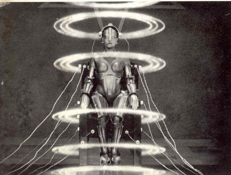
The image that I want to revisit is my Tin Man in Metropolis project from the 5th monthly challenge. We had to use spline objects. I created the tin man by combining spline tubes with an object browser figure, rigging it, and posing it to sit in a chair. Intend to do this over using all tools available. Suggestions welcome.
If you are not familiar with the classic silent movie scene, here it is. But, I intend to stay with the idea of the Tin Man in the chair.
.
Very cool! I remember seeing your work on this.
Off the top of my head, as soon as I see the similarities (and differences) in your render and the (very helpful) movie clip example, I'd say to try putting the Aura effect on your effects rings. Check the Distance Attenuation box and leave it at the default 16 to start with and see what happens. After that, maybe also try swapping the aura effect out for Glare and just try experimenting with the various settings in that. But there's a third idea of instead of (or in addition to) those effects, maybe try using Blur Object on them. I've not tried that one yet, but have been thinking about trying it.
Quick Toon Alien Character
Thought I would show the workflow for a silly alien for the animation club.
I surfed the web for toon aliens and cute aliens and that sort of thing to get some ideas. I thought that a giant furball alien would be cute, but I wasn't sure that club would use a render engine compatible with dynamic hair. I settled on a your basic 3-fingered, fat belly, antenna, no nose character. First, I sketched a couple of rough drawings to load in the vertex modeler for reference. I have a grid background for my image editor so that the perspecive sketches line up.
Note: In contrast to the reference sketch, I decided on a small snout during the modeling process.
Then it is standard vertex modeling. Load the reference images under the global tab for front and side. I started with a 3x3 cube, and then used standard box modeling for a low res model. I made sure to add geometry where there would be bends or morphs.
I applied one level of smoothing and converted to add enough vertexes for some decent morphs. I used the seams / unwrap method to uvmap the model. I created the shading domains after UVMapping. You might notice a little flourish on his chest. It can hold the alien species logo. I exported the uvmap and placed a logo that I rendered there. The logo area has its own shading domain so that I can use procedural shaders for the rest of the model.
I made some insect eyes as separate objs. I created morph areas and at least one morph for each mesh. That way, it is easier to add morphs after the skeleton is attached. I created separate morph areas for the head and the body. For the body, I made a morph to thicken the arms. For the head I made a morph for the lips to smile. For the eyes, I made bulge morphs. Remmber to save then validate morphs.
The alien is not rigged yet, (only the left side has bones, and no constraints or IK chains yet). but here is a test render of progress thus far.
looking great!!! you'll be a pa soon be careful
He's beautiful, Diomede! Bravo!
Thanks for the comments, HW and Dart.
After creating and uvmapping the mesh, and creating morph areas and at least one morph in each, set up the bne skeleton. To do so, set up just one side (left or right), and create the constraints. Then duplicate with symmetry and the constraints will be copied as well.
- It is best to use the directional camera views to et up the bones. When you go to the FRONT camera, the mesh will be too small. Select the mesh and click 0 to move the camera to focus on the mesh.
- Start with the hip. Click in the body just above the legs. Rename the bone "Hip"
- Use the bone tool to place the next bone. Carrara will connect the next placed bone to the one currently selected. Scale them to fit within the mesh. Rename bones for convenient use, such as elbow or forearm.
- Check the other directional views (left and top) and adjust the bones so that they are within the mesh. Remember, can select the mesh and press 0 to zoom the camera to the mesh.
- The magnifying tool can also be used to focus. Use magnifying glass to zoom to a specific part, like a hand. Use 0 to return to the full mesh zoom.
- Joint constraints are created in the properties tray
- Look under the motion tab
- There is more than one way o create an IK chain. One way is to use the tool that looks like chain links. Select the begining bone, click the chain tool, and select the bone at the end of the IK chain.
- One good start is to convert all the bones to ball joints. Do this by selecting the hip bone (or other root of all bones), go to the animaiton tab, and set IK consraints. See the menu options because ou might not want to apply all settings to every bone.
- now the boring part. Go through the bones and set the desired range of motion using the three circles at the top. For example, knees can bend backward around the x axis, but not forward, but thighs can move frward and back, and side to side. You can also use the drop down menu by each circle to lock or restrict the bone.
- Repeat for each bone in each direction (ouch)