How to Rig a Prop: Cabinet Doors
 RGcincy
Posts: 2,864
RGcincy
Posts: 2,864
I recently taught myself how to rig a prop in Daz Studio. I thought I’d share what I did as it is really not that hard if you know the steps. The prop was a cabinet from the product The Briefing Room. It has non-operating bi-fold doors which is what we are going to rig. The prop loads in two parts, the doors and the cabinet body. What makes it a bit more challenging is that the door handles are part of the cabinet body, not the doors, so it’s hard to have the handles follow the doors unless you combine geometry.
I’ve broken the steps down into 5 main tasks:
- Combining the Two Parts of the Prop
- Adding Bones to the Prop
- Positioning the Bones
- Weight Mapping the Bones
- Making the Doors Move Together
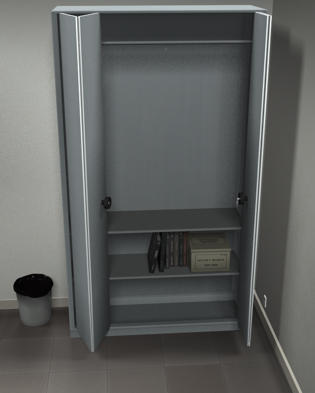
Here’s a render of the cabinet after rigging the doors and adding a primitive cylinder as a hanging rod and two primitive cubes as shelves:
If anything isn’t clear in the instructions or if adding another image would be helpful, let me know.
Although these specific steps apply to this one cabinet, you can use them for any prop. If so, you may have to reverse X and Z directions, depending upon the design and orientation of the prop you are using.
Daz 3D is part of 
Connect
DAZ Productions, Inc.
7533 S Center View Ct #4664
West Jordan, UT 84084
Licensing Agreement | Terms of Service | Privacy Policy | EULA
© 2026 Daz Productions Inc. All Rights Reserved.
Comments
Combining the Two Parts of the Prop
This image shows the two parts of the prop: the doors which move as one part, and the cabinet body with handles:
1. Load the !Pre_NorthArea into the scene.
2. Unparent the NLCabinetBody in the Scene pane.
3. Optional: Delete everything else. [I did as this make the prop more accessible in the viewport. If you don’t delete the objects, you’ll need to hide them as Obj Export will combine all visible objects into one.]
4. Select File/Export from the main menu and give your object a name and click save.
5. When the Obj Export Options dialog opens, click on Collect Maps radio button on the lower right, then click on Accept.
6. Select File/Import from the main menu and select the object you just created.
7. After the Obj Import Options dialog opens, select Daz Studio in the From: drop down box. Click on Accept.
8. You will now have a new object in the Scene pane with the cabinet geometry combined into just one part.
9. Delete or hide the original cabinet.
10. If the cabinet renders too bright, reduce the Ambient Strength settings in the Surfaces pane for all the surfaces, as the current version of DS will set the value to 100%.
Adding Bones to the Prop
1. Select the cabinet in the Scene pane.
2. Select Edit/Object/Rigging/Convert Prop to Figure… from the main menu.
3. Select Triax Weight Mapping in the Convert Prop to Figure dialog box then click Accept.
4. Go to the Tools Setting pane, and at the top, select Geometry Tool in the Active Tool drop-down box.
5. Click on one polygon in the left hand panel, then either right click in the viewport and select Geometry Selection/Select Connected or use the shorthand keys Ctrl+Shift+* (or Ctrl+* if using the number pad). This selects all the polygons associated with that door panel (each panel has many polygons on the edges which are not readily visible).
6. Right click in the viewport and select Geometry Assignment/Create Face Group from Selected and give it the name DoorLL.
7. Repeat steps 5 & 6 for the second panel giving it the name DoorL. Do the same for the third panel giving it the name DoorR and the fourth panel giving it the name DoorRR.
8. Next click on one polygon in the left handle then select Geometry Selection/Select Connected.
9. Right click in the viewport and select Geometry Assignment/Assign to Face Group/DoorL.
10. Repeat step 8 & 9 for the right handle but assign it to Face Group DoorR.
11. The right handle has a key. There are 5 separate parts to the key. Zoom in on the key, select one polygon, then hold down the Ctrl key (and keep holding it down). Select all connected by typing *, then click on another non-selected polygon, then *, and repeat until all the key is selected. Assign it to Face Group DoorR. In the left image below, the key is partially selected. In the right image, all 5 parts have been chosen.
12. Select the cabinet in the Scene pane.
13. Click on Window/Panes/Figure Setup on the main menu.
14. Click on the Figure Setup menu (icon at top with horizontal lines) and select Copy from Selected Figure.
15. Left-click on Figure Setup menu again and select Clear Hierarchy.
16. Click and drag geometry from left column and drop over top of geometry in relationships panel.
17. Click and drag bones to create parent-child hierarchy: Default-DoorLL-DoorL and Default-DoorRR-DoorR.
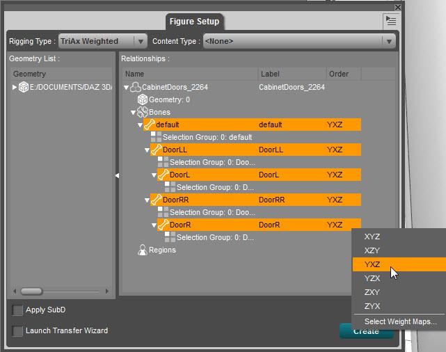
18. While holding down the Ctrl key, click on all the bones to select. Then right click on top of one of the XYZ labels and select YXZ. This will give all the bones this order. The Y, being first, will orient the bone vertically. This will also make the parameter dial Twist rotate the doors around the Y-axis
.
19. Click on Create button to make a new figure with bones
Positioning the Bones
1. You will now have two copies of the cabinet in the Scene pane, one with a name starting with the words figure (has 1 bone) and a second version with 5 bones. Delete or hide the first one.
2. Go to the Tools Setting pane and at the top, select Joint Editor in the Active Tool drop-down box.
3. In the Scene pane, select bone DoorLL. The viewport will show the selected bone in yellow.
4. Move the bone center point using the XYZ position sliders in the Joint Editor. Position it so it is just at the left edge of the left-most door panel. Change the camera view to be sure it is at the front edge of the cabinet as well.
5. Repeat step 4 for bone DoorRR, positioning it at the far right of the right most door panel.
6. Repeat step 4 for bone DoorL, positioning it on the line between the two left-most panels.
7. Repeat step 4 for bone DoorR, positioning it on the line between the two right-most panels.
8. For each of the four bones you just positioned, make the end point X and Z values match the center point X and Z values so the center and end points are aligned vertically. It’s best to do this by typing in the values rather than using the sliders.
9. You’ll notice the bones will likely have different lengths, so I made the four door bones all have the same by typing in 50 for the End Point Y value.
10. Go to the Joint Editor menu (click on the icon with the horizontal lines at the top) and select Memorize/Memorize Figure Rigging.
Weight Mapping the Bones
1. Go to the Tools Setting pane and at the top, select Node Weight Map Brush in the Active Tool drop-down box.
2. In the Scene pane, select the four door bones by holding down the Ctrl key and left clicking on each bone.
3. In the viewport, right click and select Weight Editing/Fill by Bone Selection Group(s).
4. Now the bones will move the appropriate door panels. Bone DoorLL moves that panel as well as the child bone DoorL panel. Bone DoorL only moves the DoorL panel. The same is true for the right hand doors.
5. By selecting YXZ in step 18 of the Adding Bones section, Y will be the twist axis and is the only one we will be using. You can test your bone positioning and weight mapping by moving the Twist dial parameters for all 4 doors.
6. Go to the Joint Editor menu (click on the icon with the horizontal lines at the top) and select Memorize/Memorize Figure Rigging.
7. Your prop is now ready to be used, by adjusting each of the doors in turn. In real life, though, the inner door of bi-fold doors operate both panels. The next section will describe how to link the doors together so you only have to move the inner panels (the ones with the door handles).
Making the Doors Move Together
1. Set twist for all 4 door bones to zero.
2. Select Window/Panes/Property Hierarchy from the main menu.
3. In the Property Hierarchy, select the bone DoorLL.
4. Expand its hierarchy by clicking on the triangle at the left. Expand the Y-Rotate (twist) property. Expand the Controllers property. You‘ll see a property underneath controllers called 2nd Stage (Multiply/Divide). We’ll be using this in step 7 below.
5. Select DoorL in the Scene pane.
6. Go to the Parameters pane and right click on a parameter dial and select edit mode.
7. Left click on the small [P] by the Twist dial and drag the dial to the Property Hierarchy pane and drop it on top of 2nd Stage (Multiply/Divide) for DoorLL. DoorL will now control DoorLL.
8. Repeat steps 3-4 for DoorRR, then steps 5-7 for DoorR.
9. Go to the Parameters pane and right click on a parameter dial and deselect edit mode.
10. Set twist of DoorL to 140 by typing in the value in the Parameter pane. It’s important to set the inner door first before setting the outer door. Next set the twist of DoorLL to -70.
11. Set twist of DoorR to -140 then set twist of DoorRR to 70.
12. Now when you move DoorL, DoorLL will also move and the two doors can close flat.
13. Right now the doors can be swung inside the cabinet. To prevent this, left click on the gear icon of DoorL’s Twist dial, click on Parameter Settings, then set the value of Min to 0.
14. Repeat step 13 for DoorR but set the value of Max to 0.
15. While doing steps 13 and 14, you may also want to replace the label Twist to the more understandable Open.
16. When you open DoorL or DoorR, you may notice the door pairs overlap (as shown on the right in the image below) or have a gap. To correct either of these, you need to move the DoorL or DoorR bone on the center point X-axis a small amount using the Joint Editor. It’s easiest to get the alignment right with the doors open. After adjusting the center point, copy the same X position to the end point. When done, go to the Joint Editor menu (click on the icon with the horizontal lines at the top) and select Memorize/Memorize Figure Rigging.
17. Each bone will have a number of unneeded parameter dials such as Side-Side, Bend, Scale, etc. To clean everything up, hide the unused parameter dials for each bone.
18. One way to do this is to right click on each parameter dial one by one and select Hidden/Hide Selected Properties. A more efficient way to do this is to right click on a parameter dial and select Edit Mode. Then hold down the Ctrl key, click on each unneeded dial to select it, then right click on any dial and select Hidden/Hide Selected Properties. After doing this for all 4 door bones, right click on a dial and deselect Edit Mode. I also hid Twist for bones DoorLL and DoorRR to avoid accidently upsetting the combined open-close operation.
19. I have noticed the surface of the rigged prop may lose its Default Color image. If so, go to the Surfaces pane, click on each surfaces Diffuse Color map icon and reselect the right image.
That’s it! You now have a rigged cabinet with bi-fold doors than operate by opening either door with a handle. I saved this as a Scene Subset so the cabinet can be merged with any set.
As I looked at various text and video rigging tutorials, I found two that were particularly helpful, both by Christopher Wichura:
This is excellent! Thanks for taking the time to prepare this much needed tutorial. In my experience, the free tutorials are usually much better than the commercial ones. Your tut adds yet more weight to my argument. Thanks again!
Thanks very much. Very useful :D
Laurie
Glad you found it useful. It turned out that rigging, at least for something relatively simple like this, is not as hard as I thought it would be.
This is wonderful! Thank you SO much!
Wow, great tutorial, bookmarked it for use very soon. I'm always finding parts of sets or props that I wish were rigged and have been meaning to learn to do this. Thanks for taking the time to put this together.
Thank you so much for this - You have no idea how much I appreciate that it is not a Video :)
I have bookmarked for using soon - Now I have written instructions it will make things so much easier for me
The first prop I rigged was a bus for Bryce that I wanted to use in Daz Studio. It follows a simpler work flow than this cabinet, as I didn't need to use the figure setup tool or the geometry editor. So for a simple object like a door, it may suffice. Here's the link to the bus rigging steps.
Figured out how to make a gif to show the door movement.
Thankyou for this tutorial, it's the first time I've been able to successful rig something, although I only did it with a set of double doors not the cabinet prop.
@RGcincy
I noticed in your bus post that you mention this:
"15. I observed that after the rigging is complete and you slide the parameter dial with the mouse, you’ll see the bone rotate (the white brackets in the image below) but not the door itself. However, when you release the mouse button, the door will swing into position."
I have this issue with my doors and wondered if you or anyone had a solution? I would like to see the door visibly open as I dial, just like everything else does but I don't see a solution listed here or in your bus post.
Any help?
Thanks for asking as it led me to search on Google and I found the answer. For each rigged bone, you need to add a General weight map:
1. Select a bone.
2. Select the the Node Weight Map Brush tool.
3. In the Weight Map section mid-way down, either (a) right click and select Add/General or (b) choose General from the Unused Maps drop down box and click on Add button.
4. Click on the General Weights map you just added.
5. Right click in the viewport and select Weight Editing/Fill by Bone Selections Group(s).
6. Do steps 1-5 for each bone you rigged (in my case the four door bones).
This worked for me for the cabinet. The link I found mentioned needing to do Scale Weight maps too but I found the General Map was sufficient.
I tried the same approach for the bus door (which followed a different rigging method) and I only had partial luck with those doors. Still need to track down why.
Thankyou for the quick response. Adding General Maps worked fine for me and I'll keep the Scale maps suggestion in mind too, should I ever need it in the future. I've saved off this and your bus post anyway for future reference.
Cheers for the help.
+1
(with a couple of exceptions)
I hate rigging, so thanks for this. :)
Thank you much. Your tutorial is great and helped me to understand it better.
Wow!!!!!!
Thank you so much for this!!! Incredible, I could even not imagine someone would do that with my product one day!!! The gif is already saved on my computer :)
Thank you thank you thank you!!!
Thanks to all who have commented. If you find anything unclear, let me know as I can revise it. I'll be soon adding in the info about how to do the rigging so you can see the prop actually move in the viewport.
@V3Digitimes Glad you liked it. I did a mini-review of the Briefing Room in Novica's thread yesterday - it's a versatile room.
Great!
I'll read it tomorrow, here it's the evening and I have to take care of my family! I'm impatient to read this:)
If I may offer some assistance, just select the root node, then go to the weight map brush and do the "Fill by bone selection groups" and every bone (node) on the model is done in one shot.
To make life easier for yourself for future rigging, in Daz Studio, hit F3 and this brings up the Customize window. On the right side, go to the Tool Bars tab. On the left side, scroll through and find the "Fill by bone Selection Group(s)" and drag it over to the right side to the Tool bar you want to add it too. Just make sure that tool bar is active which you can change on the activities tab. Now when you do rigging, you can easily select the weight map brush from the tool bar and have the "fill by bone selection group" right next to it for easier access and a quicker workflow.
Thanks for the tip! I'm new to this myself, so helpful to hear about other ways to do things. I'll check it out and update my write up as needed.
Cool! I read it and I made a mini mini tuto on how to light it in Iray... Using the fluorescent light tubes integrated in the subset... Well hidden, but they are here ;)
You'll see it is just like a real blind room would be lightened :)
Thank you, RGcincy for this insightful tutorial and the discussion and learning that has spawned from it! You are most appreciated. :)
The movement looks amazing. How did you made the gif?
1. In Daz Studio, I used Keymate (you could use the Timeline if you don't have Keymate) with Max frames of 30 and FPS of 15. At frames 0 and 30 the doors are closed, at frame 15 they are both open.
2. In Render Settings pane, under General, set Render Type to Image Series then render.
3. I then went to http://gifcreator.me/ to create the gif. It has you upload a series of images and you can adjust size and animation speed (I think I used 100 or 125). Select Create Animation and your gif is generated. You then download it to your computer.
Just for the little story behind it RGcincy, these cabinets, the small one and the big one are the exact replica of the ones I had in my office at my previous job. The exact one, dimensions, colors, etc...! (except that mine were full of documentation).