Trying to recreate a simple Poser candleflame shader in ShaderMixer (3Delight)
 3dcheapskate
Posts: 2,732
3dcheapskate
Posts: 2,732
I have a simple Poser candle flame shader and as mentioned here I want to recreate it in DAZ Studio.

I want to do it in ShaderMixer for 3Delight as that's the only thing I'm familiar with.
It should be quite straightforward to reproduce in Shader Mixer, shouldn't it ? A Mix brick for the Blend node, some simple maths with the normal and v texture coordinate, and a ColorRamp (I don't think Shader Mixer has an equivalent, but a couple of daisy-chained Mix bricks should work). The outputs of all this drive the Ambient Colour and Transparency.
However, I'm running into problems in ShaderMixer when I take the output of a Mix brick driven by the v-texture coordinate (preview render looks correct) and plug it into the ambient colour of the DAZ surface or whatever it's called (I don't have DS open at the moment) - the ShaderMixer preview render is okay, but the real render is just a solid colour.
.
Ignore the next several posts where I'm trying to do things with a Variable (Fixed) V brick - I should of course be using a Tiler brick to get the V texture coordinate, silly me !
My first real step in recreating the Poser shader in ShaderMixe rfor 3Delight, i.e RSL, is way down there...

Daz 3D is part of 
Connect
DAZ Productions, Inc.
7533 S Center View Ct #4664
West Jordan, UT 84084
Licensing Agreement | Terms of Service | Privacy Policy | EULA
© 2026 Daz Productions Inc. All Rights Reserved.
Comments
To start with I tried to simply connect the V texture coordinate to ambient colour. That takes a single node and a single connection in Poser but is causing me a headache in ShaderMixer
Started by importing the material from the scene.
Added a Functions > Utility > Variable (Fixed) brick and selected the 'v' variable. Plugged that into the DS Default Material ambient colour. Applied it - renders completely black.
The ShaderMixer preview makes it seem (and I vaguely recall) that V is 0.0 at the top and 1.0 at the bottom, the opposite way to Poser. So add a Math Binary brick to invert it, one minus V. Applied it - renders completely black.
Maybe it doesn't like me plugging a float output into a colour input, so I added a Functions > Utility > Color > Colour Transform to convert my float to a shade of grey. Applied it - renders completely black.
I must be missing something simple.
This is what I see in DS each time after applying the shader and rendering
Okay, there's something I'm obviously missing about (what I assume to be) the V texture coordinate brick.
If I simply put fixed values into the Color Transform brick and disconnect its inputs then the render is as I'd expect
Using values of 255 or 1 in the Color transform gives the same result, yellow [255,255,0] Using 0.5 gives a sort of khaki, [128,128,0] I'd assume.
So the three float inputs for the 1st,2nd and 3rd components of the Color Transform brick should be in the 0.0 to 1.0 range.
Now this is odd - swapping the V for U and plugging that directly into just the red of the Color Transform
That's enough for yesterday (it's tomorrow already) - time for bed, time to forget about it for a while.
The first thing I wopuild suggest is not using a Daz Default material brick - it isn't like the Poser material Room where you need to end up in the connections for a standard material, heer it's the root brick(s) thata re vital and skipping the Daz Default Material will skip the stuff you may not want (like the multiplied Ambient/Diffuse) or need.
Just tried that - doesn't seem to make any difference.
I loaded a flat square mesh, my own properly mapped UV square (third attached render shows an image applied to it before going into ShaderMixer just to confirm it's correctly mapped), to make it easier to see what's happening.
Then I opened ShaderMixer and created a simple material, Texture coordinate > Multiply > Color Transform > Surface. It should be a smooth gradient from green at V=0 to yellow at V=0, but I get this (regardless of the Value 2 in the Binary Operation Multiply - 1000, 100,10,1, 0.1, 0.01, 0.001 - see below comment about U)
With U-texture I get half green half-yellow if value 2 of binary op multiply is 1.0, but I did discover while doing this that multiplying the output of a U-texture coordinate brick (but not a V) by 0.01 as opposed to 1.0 produces some (but not correct) U dependent variation.
Going via a DS Default brick I get exactly the same as if I bypass the brick.
I must be missing something really obvious, because this is so basic.
Even simpler - in ShaderMixer just plug a U-texture directly into Surface colour, apply to my square and render in 3Delight.
Not the smooth gradient from black (left) to white (right) that I'm expecting.
EDIT: IMAGE SEEMS TO HAVE BEEN LOST
Setting Surface > Color to anything (black [0,0,0], red [255,0,0] etc) has absolutely no effect.
So I guess the input overrides the value in the brick, rather than gets multiplied by it?
Vague rusty bells ringing in the back of my head...
I've been assuming that both U and V texture coordinates are 0.0 to 1.0 as in Poser. Maybe that's where I'm going wrong ?
Test 73 - confirm that the input overrides the value in the brick, doesn't get multiplied by it:
Test 74 - so maybe I need to add a Binary Op > Multiply to scale the U/V value before plugging into the Color Transform
Test 75 It appears that I have to scale it down by around 100 to get a noticeable effect, but even then it only seems to affect the right half of the square
Test76 - make the scaling factor negative...
Looks as if U goes from -100 to +100, not 0.0 to 1.0 ?
Adding a Binary Op Add to give ((U*0.005)+0.5) and now the render looks right (at least in the ballpark)
So just change U to V, yes ?
Errr... no
.(Did I mention that ShaderMixer drives me up the wall !)
I've just noticed that Richard mentioned here yesterday that the shaders have access to the current UV values via the Tiler or Texture Tiler brick.
No mention of the Variable (Fixed) brick, which includes u, v, s and t
I had a look at those two bricks and the mention of S and T rings another very rusty old bell
So tried plugging the s/t outputs of a Tiler brick into the Surface's Color input
EDIT: IMAGE SEEMS TO HAVE BEEN LOST
Simple as that !
How foolish of me to think that 'Variable (Fixed) u' and 'Variable (Fixed) v' would give me the UV coordinates, when it's so obvious that 'Tiler s' and 'Tiler t' were what I needed.
(I'm really looking forward to the bit with the surface normal)
Okay, now that I know how to get the V texture coordinate we can get started. So here's the V texture coordinate applied to the opacity and via a color mixer (only two colours) to the ambient colour.
I saved this as a DAZ Brick Material (dbm) file ( DAZ flame 01 - the very basics.dbm ), zipped that up, and attached the zip to this post. Mainly so I don't lose it. But also for anybody who may want to play.
Next bits:
- daisy-chain a couple of Mix bricks to get the black-orange-yellow-white gradient (unless somebody can point me at a ShaderMixer equivalent to Poser's ColorRamp)
- find the ShaderMixer equivalent of Poser's Edge_Blend node - I think I spotted it yesterday, but can't find it today, so I may have dreamt it. Functions > Geometric > Special > Edge Blend
Now we're getting somewhere.
Next we add an edge blend and connect the adjusted V coordinate to its inner colour.
So the inner color of the edge blend is black at the bottom of the UV map (the ellipsoid is cylindrically mapped), white at the top, with the gradation from black to white dependent on the Binary Op Gain. The outer colour is just white.
We use this edge blended mask to drive both the Mix brick and the DS Default Surface opacity.
Next step is to get rid of the white around the bottom surface of the ellipsoid, and that's where the normal comes in. Flames go up. So if the vertical coordinate of the normal is upwards then we want things to be as in the above setup, but if the vertical component of the normal is downwards then we want to do something that gets rid of that white outer colour. In Poser I did this by doing some simple maths with the normal and V coordinate to control the Edge blend's attenuation. I should be able to the same here...
But I vaguely recall a bug in ShaderMixer's normals...
But that was nine years ago, and I did report it... (nope, that was environment mapped reflections so we should be okay)
Soooo... which brick to try ?
- Functions > Utility > Variable (Fixed) N ? ....errr, maybe not - remember u and v
- Functions > Geometric > Calculate Normal perhaps ?
Yes, if you plug a value in to an input it overrides the local value set in the brick.
Thanks for the confirmation Richard. The biggest difficulty I'm having is being so used to the Poser way of doing things, which is simply different from Studio. Not better, not worse, just different.
Anyway...
If my memory serves me right a normal is by definition a unit vector, so X² + Y² + Z² = 1, with each component being -1 to +1
In Poser I plug an N node into Ambient colour on the surface and the render gives me the normal [x,y,z] as a colour [r,g,b] like your run of the mill normal maps.
In ShaderMixer the output of the CalculateNormal brick is a vector, 3 components, so maybe I can do the same. Renders black.
Try extracting the XYZ components with an XYZ Components brick, plugging them into the 3 inputs of a Color Transform brick, and plugging the output of that into ambient colour...
...that didn't work either - renders completely black even though the previews looking so teasingly promising. I'm learning not to trust them.
So here we go again...
(P.S. I did think of using V texture coordinate again instead of the normal since for my base mesh, an ellipsoid, the normal is directly related the the V coordinate by a simple trig function)
Even this renders black
I think I'll give up for today again.
Did you try splitting the normal and then multiplying its values by 255 bfore dfedding to a colour?
No, but that gave me the key. Experimenting with a sphere primitive it would appear that each componet of the normal is -0.5 to +0.5 (so not a normal normal which would be -1 to +1), so I simply need to add 0.5 to each component to get it in range 0.0 to 1.0. Happily the binary operation can be done on a vector/normal. I can then extract the vertical (Y) component using either a Binary Op Vector Multiply or an XYZ Components*.
However, Calculate Normal appears to calculate the normal in camera space, so I use an NTransform instead.
* I have both in the diagram above - the Binary Op Vector Multiply is spurious
I admit I've never broken the normal down into its components and analysed them, but I did have a network for two-sided materials which took the normal (from a variable brick) and dot producted it with the eye vector to get a test for the facing, which worked as expected.
Okay, we're getting closer.
I now have the shader using the surface normal as well as the v texture coordinate and edge blend, and it's working more or less the same as the Poser version. The biggest difference I see (apart from the colours being just orange-white) is that the colour change gradient appears more or less the same for the centre and sides of the flame instead of being higher at the centre to create that nice curve. Hopefully a bit of fiddling with the edge blend's attenuation and/or one or two other parameters should fix that.
I still need to expand the Mix to use four colours, black-orange-yellow-white and need to think a bit more about the best way to do that.
Here's a screenshot of the shader, and I've again attached the zipped up DBM if anybody wants to play.
I think I've got the ColorRamp equivalent now - this is JUST the ColorRamp, so I now need to incorporate this into the N, V, EdgeBlend shader.
Screenshot below (shader applied to candleflame and to a properly UV mapped square), and zipped DBM attached
The blending between black and orange looks rather different - less red, less saturated than I had in Poser. The ShaderMixer Mix brick has a variety of blending modes and I just used the default. Also the yellow and orange in the Poser screenshot are slightly different (ColorRamp defaults). Still, I've got a good four colour black-orange-yellow-white blend now in ShaderMixer, so time to put that in the main shader
The variable brick seems to be another kettle of fish altogether, as I found out earlier trying to use one for the U, V texture coordinates !
Right, I now have a first stab at the complete recreation of that Poser flame shader in ShaderMixer for 3Delight.
Unfortunately it doesn't work properly.
But that's no surprise. It's likely that (a) I've made mistakes, and (b) some parameter values probably need to be changed from the values I used in Poser.
Here's a screenshot of the shader (it's huge!), and as usual I've attached a zipped copy of the DBM file
Remember what I'm doing here - simply trying to recreate a Poser shader that I did with just ten nodes. You can see why I don't enjoy doing this, can't you ?
In hindsight an alternative way to go about this would be to start with the GIMP sketch I posted on Renderosity (also below - coloured ellipsoids within ellipsoids) and try and create that from scratch in DAZ Studio
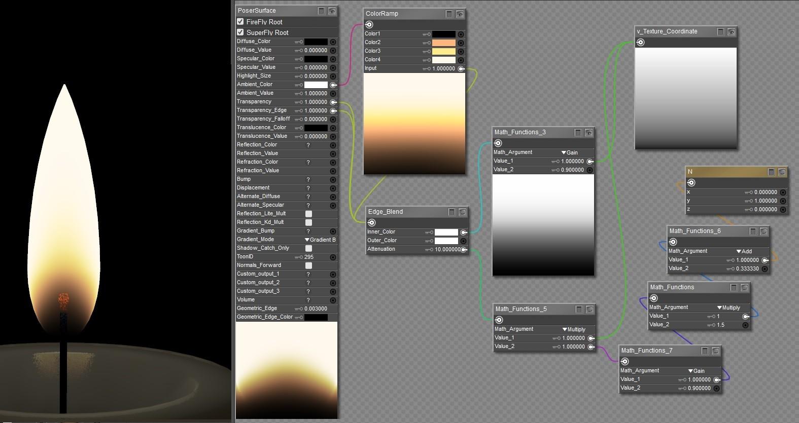
The attached composite screenshot shows the Poser shader on the left, and on the right (in roughly the same layout as the shader) the results if you plug each individual node into PoserSurface AmbientColour with no transparency.
The plan is to do something similar with the ShaderMixer network and compare the output of the Poser nodes with the correponding ShaderMixer brick outputs. I've already seen stuff that renders completely wrong, but I need to run through it in a more organized manner.
Me.
Organized.
ROFL !
One obvious thing from those renders is that my adjusted N looks very similar to the V. But since my flame mesh is a cylindrically mapped ellipsoid that shouldn't really be any surprise. The real reason for having N in there is to (hopefully) give some variation when the flame is morphed
Here's the ShaderMixer renders of the corresponding ten brick outputs. (Don't forget that ShaderMixer is outputs right, Poser is outputs left)
The output of the EdgeBlend is white around the bottom, which it shouldn't be. So that's the first (main) problem. The second problem is - why ? What's causing that ?
As I recall (I have forgotten how to scroll to see the full list of variable names, and couldn't find the page with built-in 3delight variable definitions) there is a V which is a vector and v which is a number - however, you'd probably have noticed if you had the wrong one, and there is no such ambiguity over u.
I've found three ways to see the bottom of the list:
Option 1: First select the bottom item on the list that you can see, then bring up the drop-down again. You'll be able to see a bit further down. Select the bottom item again. Repeat. Etc
Option 2: Drag another node offf the bottom of the pane as far as it will go. This brings up a vertical scroll bar that allows you to see further down the list. Repeat as often as necessary.
Option 3: Drag the variable brick to the top of the pane before clicking the variable-selection drop-down. Then option 1 or 2 as required, but you possibly won't need to repeat as often.
Regarding the variables V, u, and v - errr... perhaps you credit me with more intelligence than I have ? I hadn't spotted that !
Edit: as luck would have it I was using u and v (not V) in at least one test - but they seem to have different ranges ?
Regarding my 10 node/brick render comparison. My first reaction was that the bottom of the ellipsoid being white at the EdgeBlend's output is down to the attenuation of the EdgeBlend, so I tested with just an edge blend.
Poser on the left ShaderMixer on the right. Attenuations of (top to bottom) 0, 1, and 10
The EdgeBlend output directly controls the transparency/opacity, and contrary to what I thought was the case it looks as if the transparent area is larger in ShaderMixer for the same attenuation.
So it's not the Edge Blend attenuation itself, although it may be the thing that's driving it (i.e. inverted V times adjusted N). Or the thing that's plugged into InnerColor (V with gain applied).
(note: the camera is higher up for the DAZ renders, which I think explains why the black area is further up the ellipsoid)
Gain then ? Changing the two gain values doesn't fix the solid yellow bottom of the ellipsoid. I tried combinations 0 & 0, 1 & 1, 1 & 0, 0 & 1, 0.5 & 0.5.
I forget the attenuation multiplier: Reducing this from 10 to 9, 8, 7, 6, 5, 4 I didn't notice anything, but by 3, 2, 1 the solid yellow bottom was getting thinner. But at 0 more or less the whole bottom half of the ellipsoid vanishes. So the sweeet spot may be somewhere between 0 and 1
However, with these low attenuation values the color gradient is more or less the same across the whole flame, from edge to centre to edge, and that nice curve I want is gone.
That's enough for today.
It was option 1 I was mainly forgetting.
A rather unexpected effect - only noting it here because I think it might be useful for something completely different
I plugged the Y Component output of the XYZ Components brick straight into the 'BinOp: attenuation mult with the multiplier set to -10
A very low positive value, roughly in the range 0.01 to 0.3, seems to be required for the 'BinOp: attenuation multiplier' in order to make the bottom of the ellipsoid completely transparent. But this destroys the curving colour gradation between the edges and centre of the flame.
However, a higher value, say between 1 and 5, is required to get any sort of curvature to the gradation of colours.
It appears that I need two separate edge blends - one to control the opacity, the other to control the curvature of the colour gradation.
Maybe tomorrow.
I feel as if I'm getting nowhere here, just going round in circles.
So take a big step back.
This is the moment I realized what I was actually trying to do with a flame shader and here's the picture that went with it.
So let's forget about how I did it in Poser, and start from scratch in ShaderMixer. The main points:
- Three nested ellipsoids
- Boundaries of ellipsoids are blurred and there's an orange-yellow-white gradient going up the flame
- Gradient changes between the centre and the edges
- The bottom and the area around the wick are transparent
- (there's an additional blue area around the sides near the bottom that isn't shown - I'm ignoring that to start with as it seems separate)
Any suggestions ?