Question on Carrara's subdivision of vertex objects
 kylegonyer
Posts: 20
kylegonyer
Posts: 20
Still learning carrara and often use examples I see in other tools or techniques (that I know prior etc) and try them out in Carrara
When Extruding square faces:
It seems like you have 1 shot at it and it (as far as defining "definition" of surfaces) must start in the vertex modeling room
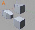
Desired result is the shape that is at the 9 o'clock position (left side of the working floor) in the image A attached
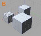
It appears it can only be made cleanly from a square that started in the room and with 1 face (1 as definition) as the 12 o'clock object cannot be "reverse subdivided" after the fact and much be at the time you drop the object or bring it etc.... see the image B
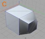
In example C the 12 o'clock shape that has the extrusion I am looking to understand and work with came from assembly room object converted to vertex In model room that case it makes the face triangulated and would result in what is seen in example C as not clean square face and edges on the extrude.
My questions are
1. Is there is any way to take a face that is triangulated on any object and convert to square face?
2. and if there is a way to even take a face that has square division and reduce them down after it is already in the workspace "reverse subdivid" I know if the face is triangulated you can at anytime increase with subdivide and control under model menu, but this would be the reverse after the fact.
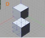
3. It also seems like subdividing a object side that is square face will yield 8 triangulated sections as opposed to less or split square faces (Image D). Anyway to not have this happen?
Hope this makes sense
Daz 3D is part of 
Connect
DAZ Productions, Inc.
7533 S Center View Ct #4664
West Jordan, UT 84084
Licensing Agreement | Terms of Service | Privacy Policy | EULA
© 2026 Daz Productions Inc. All Rights Reserved.
Comments
use the tesselation option that gives a grid
or create points and link them manually
dissolve any triangulated edges first
Thanks for your response..will give that a try, from what you said (and I need more experience) , the tesselation will make it so I can merge or connect the faces/points together and it is not so much a select the entire object and just change the faces type or defibition reduction
You can remove subdivisions (points and surface lines) by using the scissor tool to remove those points without removing the surface facing. This will reduce subdivisions and then you can move lines and points on the exisiting surface to suit your needs.
You can always use the curve tools without the use of a Square , cylinder, or sphere.
There are smoothing tools to convert faces into higher poly meshes on an object.
Example would be taking your Fig. C and using the smoothing tool to create higher mesh levels. When you convert the mesh it will then create its own additional surface points. This is handy to create more organic curves that relying on extruding, bevel, and create point tools (although can also be used in additional to option above).
One way I make shoes it actually using a series of Bézier curves, Fill Curve, Extrude, Add/remove points.
You can apply this same logic on your figures to create faces without having that weird shade depth issue you see in fig. C.
If you want to weld polygons you can use the Boolean option to cycle through Extract A>B or B>A , Weld, additional, ect ect. Boolean is great way to weld multiple options without having overlapping surfaces (Surfaces inside another polygon).
Hopefully my screenshots will help explain.
Smooth division >Subdivision level > Convert
Will use this post to show Boolean operations.
And adding and removing points/lines from a subdivisioned surface.
Understand the Boolean operations, but in another program great to see this in action here. Did not know about the sissors tool and add points, segments and split it up that way, but started seeing some examples here in the forum. It looks like you have optionjs to remove the surface facing or keep. Wow very cool. @Joanght....thank you for taking the time to upload the picts and more detail. I think some of this get's buried in the manual and/or it's just easier to see real examples. excellant!...Going to have at it tonight and see if I can wrap my head around all the options ...and I am sure what is in this post only scratches the surface around vertex face manipulation
Also if others stumble across this tread,
https://www.daz3d.com/forums/discussion/96301/modeling-objects-in-carrara-q-a-come-one-and-all/p1
this other one has a really good page 1 on cutouts and modeling links and resources....having been taking a look (of course it has gone to 50 pages now), but as a quick starter it's a nice find...Helped me some. I will continue post here related to this specifically as well and/or after trying out the ideas
I also just want to add that you can use "Link Polygons" in the dynamic extrusion tool, so you could still extrude the shape you want from the subdivided 12 o'clock in figure A.
thanks Dartenbeck, Tried that out as well...good to know
in Carrara the command dissolve is your friend
thanks Joanght, tried some boolean test and work nice...when I render it seems the hole (or partial hole that was intended) it cut with some twist and has some artifacting or could that just be my lighting and I am sure there is some way to straiten that out? probably because it is not dead even on the surface?
it's an Ngon maybe triagulate ngons or do a tesselation converging on the centre
be carefull when smoothing and booleaning at the same time
# of vertices on or around a surface plays a huge part in properly deforming an object. Make sure you have enough points/lines on a surface for boolean operations to correctly remap a surface to the existing points. Furthermore placed Points and Lines in the correct spot with the correct depth to remap the surface is essential.
Can anyone join the party?
This cube with a sheared front has a tube cut through it. The shader applied reveals the underlying mesh with SubD applied at 1x and 2x. Now, what's the 'object' lesson here?
Images below illustrate the above points. Note how in the 'final' render there is very little loss between x2 and x1 SubD. (Click to see the bigger picture) :
..In this illustration the forground object has 2x SubD, the middle ground 1x and the far objects 0x (ie none). How does this help? It keeps file sizes down to a minimum - 121 KB in this case WITHOUT any loss to detail. The foreground object also has a phong displacement shader applied.
..You probably notice that the distance objects in the above image at certain angles clearly show their low poly[gon] count. It's not so much distance from camara that matters (unless you are going to employ Depth of Field bluring), but the size on screen...
With further, quick testing I'm happy to share that 0x objects with curved surfaces should be no more than 45 pixels high in the final render to look their best, x1 objects no more than 100 pixels high, x2 objects offer greater flexibility and when coupled with bump-maps (see the first image) or displacement maps (see the second and third) can be used at much, much larger pixel sizes. Click on individual thumbnails to see the bigger picture.
A short note on the second two images...
These two images demonstrate that it is not necessary to have a high number of polygons in your mesh to have a most convincing displacement. The second image shows a reversed displacement map at a greater depth level.
Great job, FENgari.
VYusur has a tutorial on modeling circles and holes that might be useful for the OP. Sorry that finding links isn’t easy for me right now.
Thanks Diomede
Here's the simple shape and home-grown shader. You will need Philemo's Phong Displacement modifier to get the full effect !
Original file included for you to experiment with below...