First modelling effort using 2.5.2.137
 Roygee
Posts: 2,247
Roygee
Posts: 2,247
Hi all:}
Testing Hex (and my memory) Welcome any advice - especially on creating the multiple panels you see in the drawing without totally wrecking the model.
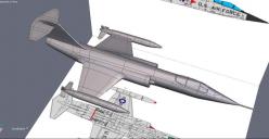
wip1.jpg
1048 x 540 - 33K
Daz 3D is part of 
Connect
DAZ Productions, Inc.
7533 S Center View Ct #4664
West Jordan, UT 84084
Licensing Agreement | Terms of Service | Privacy Policy | EULA
© 2026 Daz Productions Inc. All Rights Reserved.
Comments
This is a really good start, Roy. In general the mesh is looking pretty good. I've attached a copy with some areas highlighted that may cause concern.
First, the red box in the lower left. All that modeling and only ONE save?!?! You're truly living on the edge my friend. I suggest you use the Incremental Save (Ctrl-Shift-S on Windows) frequently. This would create "Starfighter_00", "Starfighter_01", "Starfighter_02" for you automatically. It will be a sanity saver when (not if) Hexagon crashes and you might have lost a whole evening's worth of work.
Now to the yellow circles. Those are what might be called "poles". They are places where more than 4 edges are intersecting at a single vertex. While Hexagon doesn't have any issues with them, they can cause problems when the model goes to the rendering engine (e.g. Daz Studio). When Studio tries to apply textures, etc. it can pinch in those areas. Also if Studio is applying it's own Sub Division on top of what you have done, it can mess up those areas and create "pimple" looking artifacts. We try to avoid those as much as possible even if it means having to run an entire extra edge all the way around the model. They aren't SO bad if they are in perfectly flat places, but on the curved fusalage you will be chasing those issues and getting frustrated with your results.
To your question about the access panels that are on the technical drawing. Since those would typically be designed to be flush to the surface, I usually wouldn't try to model them into the mesh. I would add those details into the texture files you'll be creating for it. If you wanted to have some sort of a little seam, then a bump map would be good enough. There's no need to add all the complexity to the mesh to model in details that should be smooth to the skin of the plane anyway.
Edit to add my annotated picture.
Thank you, JohnnyRay - I'll see what I can do to eliminate the poles. Those are all the result of extrusions - could you suggest how to avoid poles in extrusions and still maintain quads?
Incremental savings is a good habit to get into -I never really had any problems with Hex stability in the past, but belt and braces on any software is good policy:)
I'm looking for some assistance on UV mapping approaches. In the past, I used UU3D. Could cut the model into components to map each using whatever method was appropriate to the shape of the component. Those could be nicely laid out on a single map, in proportion, or on separate maps. Somehow I lost UU3D when transferring apps to my new computer. UU3D has since moved to a newer version, which I don't want to be buying just yet and the owner is not willing to let me have an old version or try to find my licence number.
I'm thinking that there are two basic ways I can go about this. The first is to keep the components separate as they were modelled, map each one and export each as an .obj to the free version of UV Mapper. The other is to weld them all together as one object, map them in Hex, but not try to fit them all on the tiny mapping space Hex gives and export that to UV Mapper.
I'd really appreciate some advice on the best approach - don't want to waste a lot of time on a hit and miss experiment.
OK, tried a different technique, instead of extruding I modelled the engine and wing and joined them. Still got the five-point poles, but managed to redirect the edge flows to where they were either eliminated or placed where they wouldn't cause pinching.
The UV mapping in Hex went rather well - I'm going to try using UV Mapper to make my templates - never used it for this before, so another learning curve!
Slapped on some procedural textures and rendered in Carrara to see whether the modelling worked - only problem I see is the canopy frame, which will have to be re-worked.
I'll put on markings once I get the UV templates working.
Cheers
Roy
Sorry for the delay Roygee, the wife and I have been on a little trip.
One of the things I thought you might want to try is to add a few extra tesselations before and after the extrusions, I realise you will know what I mean but I'll add a screen grab for our newer Hexers' (add 2 levels of smoothing to see the difference).
Hi John
Good hint - I would always put in an extra edge around the extrusion, but never thought of doing so arounf the source - still gives a 5-point pole, though, although this doesn't seem to cause a pinching problem:}
I'm almost done with this model - had the devil of a time trying to get a decent unwrap in the free version of UV Mapper. Seems to me I can get something usable if I do some colour-grouping before exporting from Hex - I'll try that tomorrow. Seems if I do that there is no need to unwrap in Hex? I was really spoilt using UU3D!
The starfighter is a pretty plane, really nice lines to it. And you've done well building it in 3D. :)
As for the poles, a lot of times it depends on where they fall. The more radical the curves of the surfaces around the poles the worse the artifacts are going to be. A pole in the middle of a flat surface would barely be noticeable. For instance from my own work, I had a cylinder for a steampunk shotgun I'm working on that initially had some bad poles right at the corners of the chambers for the shells.
[full size image]
I added some edges both length wise and around the cylinder to eliminate them. There were still some poles within the chambers, but since they were on flat surfaces, and I knew they'd be covered by the shotgun shells I didn't worry about also cleaning those up.
[full size image]
Also wanted to mention I'm a big fan of Ultimate Unwrap 3D myself. Unwrapping and cleaning up the UV map in Hex really depends on what you want to do with it. If you want to actually create 2D textures, then the overlapping mess that Hex makes of it's automapping would be a major pain. But if you're going to use procedural type textures or just repeating tileable materials then untangling them isn't as important.
I would defintiely, though work on defining domains and materials in Hex before trying to unwrap the whole thing. It can certainly save you a lot of headache to already have some of the segments of the model defined like that. Even with UU3D I still go to that effort because it makes it easier to unwrap based on material zones than trying to define them in UU3D and do it from there (at least I find it easier that way). I also use it by making the colors look really wild and contrasting in Hexagon because it can help me find places where there's an issue flowing from one surface to another. Like in my second screenshot by having the chambers purple while the main body was aqua I could see if there was anywhere that was poking through from one surface to the other.
Neat model, progress and information here.