Seamless lattices
 Apoc
Posts: 407
Apoc
Posts: 407
I am currently working on a project of mines and I need a bit of help, concerning lattices in Bryce.
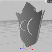
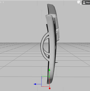
When Bryce creates symmetrical lattices, there is always a line down the middle of the lattice to where it joins. I have tried numerous methods, ( even exporting and working on it with a different program ). But I cant seem to find a way to remove the seam from the joined lattices.
Methods I have tried
- splitting it in half via boolean procedure, then rejoining it.
x - why it fails = this still makes the seam visible, and causes a unwanted amount of information in the middle of the object.
- Smoothing out the picture/terrain canvas completely
x - why it fails = even if the its a perfect circle or straight line, bryce still joins both sides together with a seam
- exporting it into another 3d application
x - why it fails = when I exported it and tried to reduce the visibility of the seam, it occurred to me that the seam is more like stitches. Bryce merely takes an object, flip it, then pastes it together with slight vertices connecting it. if I were to fix every vertex connected, I would have to do it by hand as I do not know a way to automatically closes them, and this would take hours upon weeks for more complex lattices.
So if anyone knows of any way to remove the seam / line, in the middle of a symmetrical lattice, I would be grateful to know. At the moment, I am at a loss.
Daz 3D is part of 
Connect
DAZ Productions, Inc.
7533 S Center View Ct #4664
West Jordan, UT 84084
Licensing Agreement | Terms of Service | Privacy Policy | EULA
© 2026 Daz Productions Inc. All Rights Reserved.
Comments
Hi Apoc,
The news isn't going to be good I'm afraid... Though someone may know better than me, so don't take my word for it.
When we use symlats in Bryce, we can almost always disguise any showing seam with texture. The problem you're having is that you're not using it for a landscape so don't have that luxury. I don't know of a way of getting rid of it. As you say, Bryce simply flips the heightmap and creates a mirror of the geometry it makes for one half then somehow (using voodoo magic or something) joins them together. There is no way within Bryce to edit the geometry of terrain objects apart from by amending the heightmap.
Another thing that 'may' make it less obvious is to make sure the symlat is set to "Solid" in the Terrain Editor... See my highlighted part in the attachment below. But really, all that will do is to make sure there are no black voids between the two halves.
You could try playing with some of the editing tools, maybe just a tad of round edge or gaussian
@DaveSavage yea, I figured that might be the case, but I figured there might be at least one person who has experimented beyond what I have done.
@Chohole sadly that method I have tried extensively. No matter how smooth the edges are, the transitioning from the top half of the lattice to the bottom half is where the seam appears. I might try some more experimenting to with other shapes in bryce though. Perhaps I might be able to figure something out
I have some rocks that are generated from symlats. I will go load one up and see Iff I can see how he made them
OK here we go One symlat rock formation by Estevez
When rendered it does still have the seam, but it is smoothed out a lot
As Dave said when It has a terrain mat on it the seam is not at all noticeable. I deliberately chnaged the mat
I understand you. It is very unoticeable , especially if you work with large scenes, it can be hidden very well. Sadly to say :( the project I have in mind, does not involve scenes made for bryce. It is more or less a proof of concept, and I have the entire concept worked out, except for this one small issue. The way I see it. Is that there should be a way to keep only the 1 half of the lattice ( aka the basic terrain editor ) , flip it, connect it manually , and remove the seams that way. But its just a thought.
Not sure if this moves you on any further but I've looked a bit into the seam issue and the lighting/rendering method you use has quite an effect on how noticeable the seam is.
Below are three renderings of exactly the same scene (the object on the left is a Symlat, the one on the right is a terrain which is then duplicated, flipped on it's Y axis and the two are then manually placed together. Both objects are covered in a smooth pink material from the Basic Mat library.
Render 1 is done 'premium' lit by only Bryce sun and with soft shadows enabled.
Render 2 is done 'premium' using HDRI/IBL with the Bryce sun switched off.
Render 3 is done 'premium' using only the Bryce sun and with True Ambience switched on. (It's noisy because it's only 16rpp to keep render time down)
The softer the light is, the less the seam shows.
@DaveSavage that is very interesting. Nothing that applies to me personally, but useful information none the less.
I have also done some fiddling myself with some other 3d applications and have found out why the seam might be so visible to be begin with. I think chohole might have the right idea when it came to blurring the edges.
It seems part of the problem is that vertices where the connection is made is slightly elevated compared to the rest of the model. Im certain with some more trail and errors, there might be away to make it more smoothed out. Still no luck with gaussian the edges, but perhaps my approach is wrong. hmm.
Apoc, your task is divided into two:
1. How to get rid of the gaps on the border of the upper and lower lattices.
2. How to smooth the seam by exporting to another 3D application.
I tried to solve both problems.
While I'm talking about the size of the gap.
The size of the gap on the border of the two halves depends on the shape of the height map, namely, on the steepness of the slope on the border. The gap most often appears on the north and east side of the object. To check the gap, I place the Radial Light inside the upper part of the symmetric lattice and in the top view I look at a dimly lit scene where the light penetrates.
Get rid of this gap almost fails. But sometimes it helps to smooth the height map once. You can try to change the resolution of height maps in the TE or in the 2D editor. It does not always help. Raising the bottom bracket also does not lead to the desired result, although you can try all the ways.
Here is a map of the heights and render of my experiment.
I have nothing to contribute here (sorry) but I find Slepalex's observation about the gap interesting: north and east. This is exactly where the terrain mesh extends by 0.08 Bryce Units if it is kept at the default size of 81.92 BU. This small extension north and east prevent tiled terrains to match seamless when a "Snap to" option is used.
Once I had the task of making a hanging rock with a negative slope.
Here is my old job with this rock.
http://fav.me/d4r1a1r
I decided to make a stone out of it by exporting to Wings and smooth the seam in Sculptris. Export with Sculptris did not work, because the symmetric grid consists of two objects.
Below is a height map, a render of a rock with no texture on the left and a texture (turned) on the right, a view in TE and a render of a stone that turned out to be imported / exported to Wings, Sculptris and Bryce.
Next, I will describe the whole process and the difficulties associated with it.
First, I set the maximum number of polygons to export to OBJ. Sculptris refused to load this object. Wings loaded, but it turned out that the upper and lower parts of the symmetric lattice each consist of two objects. Total 4 objects. Sew them together is no possibility. These are hundreds of vertices that make up the seam. Then I set fewer polygons. The object turned out from two parts, top and bottom. Sculptris does not accept such objects, and it is impossible to stitch them in Wings. Then I set the minimum number of polygons and everything worked out for me. It is a pity that I did not copy the whole process, but saved only the result in Bryce.
Today I repeated the experiment. I set 53616 polygons and everything worked out for me. Here are screenshots from Wings and Sculptris. I will not describe tools for smoothing in Sculptris and modifications in Wings. This is not a Bryce theme. But if you ask questions, I will gladly answer them.
The main conclusion: smooth seam in a third-party program can be. Exporting a symmetric lattice to OBJ is also possible, but you just need to calculate or determine the experimentally optimal number of polygons. After smoothing in Sculptris, we save it in OBJ and import it into Wings for further modification.
The last picture is the import in Wings of a low-poly symmetric lattice for creating a stone and modifying it.
Thanks to everyone that is helping out with this post. I have yet to find the exact answers to my dilemma, but this has been a very informative experience none the less. I am grateful for all the tips :)
@slepalex I am also using sculptris at the moment, so you don't have to bother explaining, it is a very straight forward program and convenient as well. About the gap problem you mentioned. I never knew there was a solution for it. Usually I am very careful with my procedures so I have never personally ran into it. The picture you see in the original post was actually just me fiddling around with sculptris trying to blend the seams with the base model ;P whoops. thought I clear that up.
About smoothing seams with 3rd party applications, I figure that might be the only way, but for this, however, would you happen to know a more streamlined method of achieving this? It is not difficult for me, but I think it is only proper that I explain to you all what exactly I am trying to accomplish.


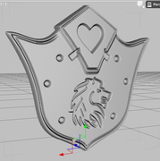

What essentially I wish to accomplish is a proof of concept of what can be achieved with bryce.
The idea is, that if an image is made well enough, with the right information put into it, bryce would be able to generate a functional 3d model using only that image.
Curvature, and details can all be applied to the image, without having any skills / or patience for 3d modeling. Effectly making it a quicker ( in theory ) way to model if one was willing too.
For non organic objects, it is easy to modify the shape by subtracting it with a boolean procedure. The problem occurs however, is when you have organic shapes, shapes that need special curves.
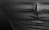
Now, one can essentially create a mask for the object, and use that as a subtraction, to complete the objects shape,
but when that is done, there is still one glaring issue to overcome. And that is that the seam still becomes visible.
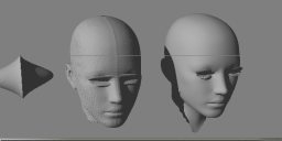
I am able to copy the curvature and the shape of an image fairly accurately I would say, and have also figured out how to copy irregular shapes for more organic images. People
The only down side with this procedure however is that the lattices / terrains, always wish to inject a seam. If I could solve that one slight problem, I am fairly confident, one can create a boundless amount of easy to make 3d models within a few minutes, if given the time.
I was actively engaged in modeling in Corel Bryce 5 in the 2000s.
The coin, horseshoe, chess horse and the lock on the chessboard are made of a symmetrical lattice, the rest is made of Bryce primitives.
Heightmaps are mostly made in CorelDraw.