Splitting parts of a model, possible with Hexagon?
 nDelphi
Posts: 1,968
nDelphi
Posts: 1,968
This is a question coming from a person with no clue whatsoever on modeling.
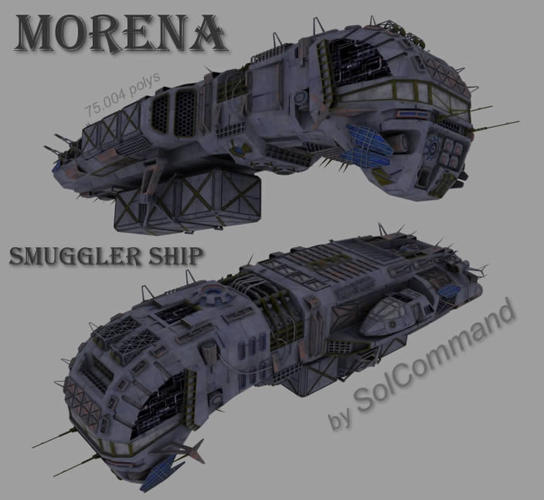
I was in need of a very specific class of space ship, a cargo ship, and I found a model that seems to render quite good in DAZ Studio 4. The problem is that the model, although textured, is in object format and the accessories it brings are tied all together; like a small shuttle on the side of the main ship and several containers.
Is it possible to remove these containers and the shuttle and maintain the texture while doing it in Hexagon? If this is possible, any explanation, especially videos tutorials on how to get that done will be appreciated.
Here is a picture of the model:
Daz 3D is part of 
Connect
DAZ Productions, Inc.
7533 S Center View Ct #4664
West Jordan, UT 84084
Licensing Agreement | Terms of Service | Privacy Policy | EULA
© 2026 Daz Productions Inc. All Rights Reserved.
Comments
Not sure if there would be a copyright issue with what you intend to do, or if this would work, but try - Select a face on the unwanted part, use the + key to grow that selection and press the delete key. With any luck that should work (fingers crossed).
No issues, this is a free model with the usual freebie license type agreement of giving recognition when used in a project, for personal and commercial use, and not packaging it after modifications and making it available to others (at least not without permission).
I will try your suggestion, thanks.
My question is totally meaningless to what I want to do. I want to be able to split the containers and the shuttle from the haul of the ship and use them as separate props/objects. Not just get rid of them.
Does the model show as a single item in the properties panel? If so, you can detach parts by selecting them and hitting "Vertex modeling ->Extract". That will make a separate form or shape, that you can rename to suit. If the model is UV mapped and textured, you'll lose both UV map and texture - no way around that.
An idea occurred to me and just tried it out
If you select the faces of the parts you want to separate and copy/paste them, those parts retain their UV mapping and so does the original. You could then make new shading domains for those parts on the original and set the transparency to 100%. You would lose the texturing, but if it has been well UV mapped, you should be able to put the textures back on without any problem.
Use the same original texture map for the copied parts.
When you render, you can hide or unhide the new parts, as required.
Depending on how the modelling has been done and what angle of view you will be using, you may find apparent holes where parts of the model are transparent. You can disguise these by modelling in some mesh, UV mapping and texturing to match - don't physically attach them to the model, just group them.
I read this thread earlier, but logged out, and went to double check my technique before I posted.
Roygee's last post is the technique I was going to tell you to use (easy to do), but with one major difference. No transparency settings, but recreate all the parts you want separated from the main mesh (boxes, shuttle, main ship, etc.).
Yes, it does retain both the Shader Zones, and the texture data, but the way I do it is via DSPro4.5 and Hexagon.
First I load the model into DS, and then transfer it over to Hex via the bridge. Next select all facets belonging to whatever "part" you want to create (example: All the shuttle's facets), and then do a copy/paste.
You have now created a new mesh, but it will labeled something like "form3". Just rename it to "shuttle" (or whatever you like). Keep doing this for every separate part you want created, including the main ship, minus all the other parts you created.
Now, just delete the original all-in-one mesh, and you will see you still have everything (and in place), but you can select each individual models to do with as you please.
Last, select all the meshes, and use the send-to DS button. DS should populate with all the meshes you just created, and all in proper location. You can now move them till your hearts content.
If you want to move them all together (move main ship, everything stays in place, and follows) then either parent all the smaller models to the main ship, or just create a new group with everything in it. Just select the group parameter in the scene tab, and move that when you want to move everything.
Don't forget to save it all to your library. I usually save the main prop, but parent all the smaller props to it, so I can load them all in place connected to the main prop. I've found with DSPro4.5 that it will not save the entirety of parented props, and you have to save each individual piece. I save the main prop in a folder, and then create a sub-folder containing all the parented props. You can just save them all to the same folder, though.
Hope this helps, good luck...
Yes, better and simpler:)
Thanks guys for the help. I really appreciate it. I need to understand Hexagon's interface and some modeling terminology to get this done but I know what to do now.
I was mistaken about the textures. The textures actually have to be applied after the model is loaded into DAZ Studio. I forgot about that bit of info.
That out of the way the only thing I needed to worry about was the mesh itself. After splitting the bottom containers from the model, I noticed that the model was loading with some issues, some polygons are missing showing a broken mesh? (See the image).
Any ideas why this is happening? I tried with DS 3, and DS 4.5, and Hexagon itself, to import the model and it ends the same way.
BTW the model is located at:
http://www.sharecg.com/v/57992/related/5/3D-Model/Morena-Smuggler-Ship
Those look like they could be rendering artifacts due to some anomaly in, or introduced into the mesh itself.
Did you use the copy/paste method?
If so, you might have missed some facets that could have introduced the anomalies.
Were those facets like that in the mesh before you started your surgery?
Also, note Roygee's post above mine. He gave the best insight into how to handle any holes in the mesh that could be introduced when you remove other parts of the mesh. Although, it does not appear there was anything extracted in the locations where the artifacting appears, so I would probably rule this out in this case.
Example; When you remove (create new model from) the shuttle, the landing pad directly underneath the shuttle could be nonexistent, and you would have to use Roygee's modeling trick to fill in the gaps (without disturbing original mesh, and Shader/Texture data).
Please post a "wire" screenshot (showing all individual facets with surrounding edge lines) closeup, so we can inspect what might possibly be wrong. The wires usually will tell the tale, and it could be something as easy as inverted normals, or coincident facet issues.
The facets might be truly missing, and in that case, the simple fix would be to reselect the original mesh to include them again.
A simple trick to make sure you are selecting all the necessary facets is to use marquee selection in wire-frame mode, and taking care not to select any unwanted polys/facets (like the cargo boxes, or shuttle). It allows you to select any hidden, or hard to select facets you might have missed. Also, this can be used in conjunction with "add to/grow" selection, but this can be tricky if what you don't want selected falls under same shader domain (it could inadvertently select polys you don't want selected for copy/paste).
*EDIT: I downloaded the model, and I will take a quick look to see if there is anything wrong with the mesh in those areas before any surgery attempts.
I really need to explain myself better in future posts.
Yes, those are like that when I import the model, before I do any surgery.
They look more prominent textured, I didn't think wired would help much to show the problem. The issue is definitely the mesh.
O.K., I'm back...
In the immortal words of Peter:
"Holy crip, it's a crapple!"
No worries, nDelphi, we just have to assume things when people don't detail all accounts of an issue.
O.K., I took a look at the model. Even though it is a very pretty model, and highly detailed, it is by far a model for DS/Poser. That is why it is listed on ShareCG under 3D Models as opposed to Poser, or DS sections.
For it's intended usage (probably a rendering software that reads smooth groups in the OBJ) the model is fine. Not great, but fine. He puts up the poly count like it is some kind of badge of honor, and all I see is where he could have saved on polys, corrected mesh issues, and created proper smooth groups. It's not my model, so I could care less, but for a newbie such as yourself trying to use this monstrosity in DS/Poser, and/or making any jury-rigs to the mesh, I feel bad for you or anyone else attempting it.
One thing I love about DS is it will show all anomalies in the mesh, and point out all the artifacting in meshes not intended for DS/Poser.
DS/Poser do not read smoothing groups (set hard edges) properly, so either the modeler needs to compensate, or the software does (like Poser's ability to set smooth angles).
This mesh is a train wreck for purposes of DS/Poser, and not only does it contain one Material/Shader domain, It was UV-ed via per-facet. Probably to have no stretching issues per facet, and (author probably has) 3D painting across seams software. Would be a nightmare to try and paint that 2D map.
The author has created this model with every edge being hard edged (all facets with individual smooth grouping), and disregarded any natural smooth objects such as spheres, columns, and etc. Not an issue for DS, though, as DS doesn't care.
Hexagon, however, does read the smoothing groups in the OBJ file, so nothing looks wrong with the mesh in Hex.
A proper model like this for DS/Poser requires mechanical beveling of all intended hard edge data, or coincident facet separation to be viewed correctly.
The artifacting in those spots you show are due to how DS reads quad data structure. Even though there are no n-gons, the author either performed unnecessary weld triangulation on perfectly good quads, or (as in the artifact instances) has non-planar straight quads that need triangulation to rectify the anomalies.
In other words, the simple fix for you to do is to just triangulate (3 point triangle) the quads (4 point polygon/facet) of the offending facets. You can either do this by hand using the connect vertices tool, or auto triangulating by selecting poly, and using the triangulate facet tool. It should correct your issues.
Below are some pics showing what I mean. You can see the artifacting clearly in DS, but looks fine in Hex. I created a separate shader domain for one offending facet, and hid it. You can see the four vertices that make up that quad (and one to left of it). The three vertices in a straight line are what are causing the anomalies. These quads need to be triangulated.
In the Wings3D pics you can see the hard edge data clearly. All the edges are orange (hard edge view setting in W3D) on the mesh. You can see how nice the model looks in shaded mode, but this is only good for a handful of software/renderers.
I also included a screenshot of the UV's. I selected one UV group, and you can see it's placement on the map.
Hi DaremoK3,
Since which version?
I have never seen Hexagon read smoothing group information from .obj format. It does automatically create smoothing groups, but that is hard_coded and not user controllable.
3d programmes that handle smoothing group information correctly, will also give you a way to define them, either by hard_edges or by actual polygon groups (or both).
With, for example, Wings3d, that uses hard_edges that spit the polygons into smoothing groups, and will write that information(if option enabled) into the .obj file. But if you then load that into Hexagon, it will replace any smoothing groups with its own.
You can easily check yourself. In wings, create a sphere, select edge_loop around its equator and set hard_edge. If you then (in wings) set view to smooth shading, you will see the 2 smoothing groups (top/bottom). Export to .obj(make sure .obj export is set with option to export normals/smoothing groups) and load it into Hexagon. The sphere will now just have one smoothing group.
I have been trying to get this done but no luck so far. I am just too new to all this.
I thank you for all your explanations, but I am afraid to ask if you could give me a step by step to follow? Or anyone else for that matter.
I get this a lot:
"No facets with more than four points or no object selected."
I managed to fix the mesh with the help of LithUnwrap.
I just used the command Triangulate Model under Tools.
For whatever reason, I could only fix the bottom of the mesh in Hexagon, when I tried the sides of the model and the one at the top above the cockpit they just would not seal. It has to be my lack knowledge since I am sure Hexagon in the right hands can get it done.
Anyway, thanks for the help and pointing me in the right direction!