Adjusting the Historical Armour after AutoFit
 Richard Haseltine
Posts: 110,371
Richard Haseltine
Posts: 110,371
I promised I'd do a walk-through of a process for tidying up the V4 Historic Armour after using AutoFit to transfer it to Genesis if it won a place in the Members' Choice poll. I haven't tried this on all parts, I suspect some may be better left alone or only partially modified, but the steps I am going to cover are purely mechanical - just clicking buttons and picking things from menus, no skill with painting weight-maps or adjusting joints required - so it is something anyone can try.
Setting up
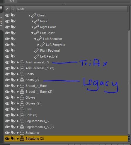
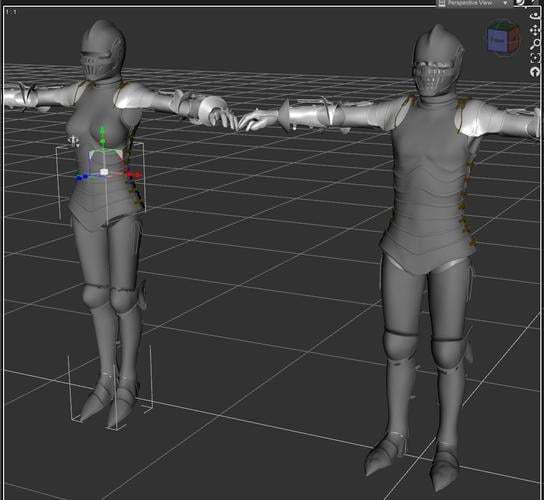
Although I'm going to cover only the leg harness in this thread, I loaded all of the pieces of the Historic Armour twice - once AutoFitting them to Genesis and once cancelling AutoFit to leave them unattached. Then I slid the unfitted, unconverted pieces off to one side (actually I slid one, copied its setting, and pasted them to all of the other pieces). The first image shows the viewport, the second shows the scene pane - note the different icons for a TriAx figure and for a legacy parametric figure.
Daz 3D is part of 
Connect
DAZ Productions, Inc.
7533 S Center View Ct #4664
West Jordan, UT 84084
Licensing Agreement | Terms of Service | Privacy Policy | EULA
© 2026 Daz Productions Inc. All Rights Reserved.
Comments
What needs adjusting
AutoFit blindly assigns the Genesis bones to the target item and then projects the weights that control bending, That's well and good for most clothing, but with something made of rigid segments like armour the results can be poor - and extra bones, such as the adjustable knee pieces in the Historic Armour, are lost in the process.
As a guide to what we can usefully do to improve the converted armour we need to look at the original V4 armour to see how the bones were set up. The first image shows the V4 Sabatons in the Tool settings pane, with the Joint editor Tool active. Using the marked drop-down we can select the different parameters to see their settings, and to edit them (the default for this tool is Centre/End point, which we will need later on). The next image shows the lFoot bone of the V4 Sabatons, with the xRot(Bend) parameter selected in Tool Settings. From the gradient in the weight-map we can see that it actually uses falloffs: the weight-stripping process I'm going to suggest therefore won't be applicable here, though it might be possible to break each plate out as a separate bone - but that's definitely going to be left as an exercise/experiment for the reader.
If we now look at the leg harness, however, the shin is green all over, meaning that it's set up to move as a unit - that's an ideal candidate for the process I'm going to suggest. The same is true of the thigh of the harness.
If we look at the knee of the harness, there are three special bones, not present in V4, covering the junction between thigh and shin. If we click their visibility off and on we can see that they are separate pieces of mesh, not attached to the mesh for the other parts of the harness - this is going to be a big help in making the joints on the converted figure work as the originals did.
Re-grouping the mesh 1
Although TriAx rigging doesn't absolutely require that a bone have an associated group, assigning the parts of the knee joints to their original groups will make it easier to edit their weights later, and to allow their visibility to be toggled. it should also make sure that the converted figure will load corectly in Poser using the DSON Importer.
Fortunately although the AutoFit process has assigned all of the mesh to the groups of the Genesis figure it hasn't deleted the groups used by the extra bones, merely left them empty (see the first image, showing the Tool Settings pane with the Polygon Selection tool active - the groups are there but contain 0 polygons). The conversion process has also assigned some bits of the mesh to the hip and to the feet - those groups should also have 0 polygons. (The other 0 polygon groups belong to the laces on the sides of the hips. I'm not going to be reinstating those right now, as it would be slightly fiddlier - probably needing the gradient mode of the weight painting tool.)
As noted in the last post, the cop and the shin1 and shin2 parts are self-contained mesh - that's going to make it really easy to reassign the mesh. With the Polygon Selection Tool active click on part of the left Cop to select a polygon (second image). Next, right-click and from the menu go to Polygon Selection>Select All Connected - or just press ctrl(Win)/cmd(Mac)* - to select the whole mesh section (third image). Now right-click again and this time select Polygon Assignment>Assign to Face Group>lCop. Finally right-click and go to Polygon Selection>Clear Selection. Repeat for the other knee parts on both legs, clicking to select a single polygon (or more, it doesn't matter if you catch more than one as long as they are part of the same piece of mesh), selecting all connected, assigning to the group, and deselecting.
Re-grouping the mesh 2
Now, if we select the whole of the left shin by clicking the + next to lShin in Tool Settings we will see that it's missing some bits at the bottom - AutoFit has assigned them to the foot instead. With the shin polygons still selected right-click, Polygon Selection>Select All Connected, then right-click, Polygon Assignment>Assign to Face Group>lShin to fix this (and to cause another problem that I missed until later - on reflection it would have been better simply to click the + next to lFoot in the Tool Settings pane, then to do the Assign to Face Group>lShin, but I'm leaving my goof as a warning).
As you can see from the second image, AutoFit also assigned some polygons from the bottom of one of the thigh pieces to the shin and when I did Select All Connected it grabbed the whole of the thigh's front plate too, and that's now part of the shin. To fix this just clear the selection, then select one polygon on the thigh piece, right-click Polygon Selection>Select All Connected, right-click, Polygon Assignment>Assign to Face Group>lThigh. Now we are just left with the bits of the thighs assigned to the hip - unfortunately, since there's only the one hip with bits of two thighs we can't simply click the + next to the hip in Tool Settings and then assign to a thigh - but since we have now tidied up all of the other odd assignments we can do a final round of selecting ech thigh in turn from Tool Settings, selecting the connected polygons, and assigning to the thigh again.
At the end of this we should have all of the groups correctly set up, as in the last image.
Creating the extra bones
We've split the mesh up to get the extra knee pieces, but we don't yet have them as bones that can be adjusted on their own. That comes next.
First, we need to remind ourselves of how the extra bones fit into the skeleton. If you look in the scene pane with one leg of both the V4 and the Genesis leg harness expanded you will see that all three pieces are attached to the thigh bone, and are siblings of the regular shin bone. We therefore need to create three new bones as children of Left Thigh in the AutoFit figure. If you activate the Joint Editor tool and select each of the knee bones in the V4 leg harness, you can see their rotation order in the Tool Settings pane (no picture, but it's just to the right of the drop-down for selecting the parameter in the first screenshot in the second post) - it's YZX for each piece (meaning the bone would twist around the vertical axis, and that its biggest bend is going to be around the side-to-side axis); in this case that's easy enough to remember but in general you may want to note the rotation order down.
To create a new child bone, you need to be using the Joint Editor tool and to have the bone you wish to be the parent selected - lThigh here. Right-click on the bone and from the menu choose Create>Create Child Bone..., then in the dialogue enter the name of the bone (same as the group name) and set the rotation order - if the name is too cryptic you can type something more informative in the label box, otherwise the label will copy the name. Finally, to allow a user to click on the mesh to select the bone, we need to use the Tool Settings pane again to set the selection group - just click on the button next to Selection Group and check the group to use. Repeat for the other two left knee parts, reselecting the thigh each time before creating the bone, then create children of the right thigh for the right knee parts
Setting up the bones
Now we have our bones, but they are using default settings (and don't have any effect at all on the mesh).
One obvious way in which the default settings have not been helpful is in the orientation of the bones. Still with the Joint Editor Tool active select the lShin2 bone on the V4 leggings - the bone points down to the heel (in fact it is coincident with the regular shin, as are the other two knee piece bones). Selecting the same bone in the Genesis leggings it points up to the hip. Fortunately this is a simple fix. If the Tool settings pane is currently showing options for any of the bend parameters, click the drop-down list (highlighted in the second post) and select Centre/Endpoint. Select the lShin and copy the x value for Endpoint from the tool Settings pane (just click on the number, drag to highlight and hit ctrl-c or right-click and Copy), then select each of the knee pieces and paste that value in for the x value of their endpoints (click on the number, highlight, and paste). Repeat for the y and z values for the end point.
Now the bone end doesn't actually touch the red endpoint marker, and doesn't match the shin's bone marker - that's because the bone was created along the y axis, but it actually needs to be slightly off-axis (the rotation order is only a first approximation in most cases). This is another simple fix - select each knee bone in turn, right-click and select Align>Align Node.
Weighting the bones 1
Now we have our bones, but they still don’t have any effect at all on the mesh. Time to assign their weights, and to tidy up the weights on the existing bones. Switch to the Weight Painting tool - the Tool Settings pane changes to show options for the tool, which we won't need, and a list of weight-maps.
Select the lShin in the Scene pane (you can't select bones with the Weight Painting tool) and highlight the XRotation map in Tool Settings: you will see that the weight colours vary along the bone, unlike the solid green of the V4 original. Note also that there are maps for the X Bulges - deformations of the mesh when the joint bends, to fake muscle compression, which were not enabled in the V4 version of the figure.
Now switch the selection in the Scene pane to the lCop - this is solid blue, meaning that it won't have any effect on the mesh at all.
We want all of the bones to be solid red for their own rotations (red for weight-maps is the equivalent of green for falloffs), and solid blue for all other rotations.
Weighting the bones 2
Setting the weights is, in this case, pretty simple since we want the values to be uniform across each bone - select the bone's group, select each weight map in turn, fill with the desired value. I will go through the steps for the lShin below - the process needs to be repeated for the other bones in the harness, starting at the bottom and working up to the thighs.
Select the bone in the Scene pane, and with the Weight Painting tool active select the weight map for XRotation in the Tool Settings pane. Right-click on the bone in the viewport and from the menu go to Polygon Selection>Select>Face groups>lShin. Then right-click and select Fill selected faces..., and in the dialogue make sure the slider is all the way to the right (100%) before clicking Accept. Repeat for the other two rotations. For the new bones for the knee plates that will be all that's needed, but for the shins and thighs we also wanted to remove the bulges - in the Tool Settings pane right-click on each active bulge map and from the menu select Remove Selected.
The end result
Although there are quite a lot of steps, it is fairly quick to do (when you aren't taking notes, at least). Posing the harness with the left leg modified and the right leg as AutoFitted you can see that the knees are much less distorted, and more armour-like, though there's some poke-through on the thigh just over the knee; fortunately applying a Smoothing Modifier fixed that without badly affecting the overall appearance (first and second images).
As noted in the first post, where the original bones have a fade from green to red when selected with the Joint Editor tool and a rotation parameter selected in the Tool Settings pane they won't be improved by this process (though if you are willing to try painting weights, rather than use flood fill as here, in the final stages the earlier stages above will help prepare the way) but where the mesh is set up to move as a unit this process will go a long way to restoring the original behaviour.
Trying the method out on the rest of the armour is, in the time-honoured phrase, left as an exercise for the reader.
Wow...this is really useful! Thanks Richard... : )
You're welcome.