-
Importing 3d models from Blender/Maya to Daz Studio
Generally, expect to retexture in Studio...
The obj format is very picky about textures and where they image files are located...it doesn't handle complex directory structures very well and doesn't like things like spaces in names. FBX and Collada are somewhat better...but they have other import problems in Studio (like rigging is difficult to impossible to import and tend to be very picky about scaling and transforms).
Also, the obj format is limited on what it can attach as a base texture...basically a diffuse color/image map, bump and opacity/transparency. So if you aren't doing an image based diffuse, then there's even less to import to begin with.
So the easiest thing to do is collect your maps in a central location (usually a folder just for that item) that can be dropped into the Studio texture folder and reassign them once every thing is imported into Studio. That way, when you save it out as a prop or figure, the files will already be in the correct location.
sorry if i ask im still new to 3d. u said about putting my maps in central locations. do you mean texture maps or baked maps? Do i have to bake the maps into normal maps, ambient occlusion maps and so on in my 3d modeller after texturing before importing to daz? or can i just texture the model, uv map it and then export as fbx or obj files?
Encryption isn't the real problem with 4.9...- - -
Can someone from official DAZ Staff clear this up?
Is there a way to use backups from /cloud folders on a different pc?
And if so how does the activation happen?
There is good news and bad news on this one.
The bad news is that an easy way to share cloud installed files between multiple machines was on the TODO for 4.9, but didn't make it TODONE for 4.9. It's not the encryption that is holding anything back, it was all built with the intention of being able to be shared between multiple machines that you owned. Because the database is such a central part of the new Daz Connect system if it doesn't believe the file is there then the rest of the system believes it. I had built a system earlier in the 4.9 pre-beta days but it made syncing slower than a snail in a Manitoba winter while having as many corner cases as a six dimensional dodecahedron, so it was wisely pulled out.
The good news is that the workaround is just telling Daz Studio to reinstall the things that it previously had installed. Hardly any bandwidth will be used (just transferring some checksum files) and it will scan the files on your drive to make sure they are the latest version according to the server and then will mark them in the database as existing, fetching anything that is out of date. Even the metadata is cached to prevent having to redownload. I have heard that this would be pretty easy to script, but I have not yet heard of anyone giving it a try.
Thank you for clearing that up. This sounds like a promising solution.
Maybe just one issue that could happen with the workaround:
If you do not know which files are included in the backup and install a different selection on the new computer you may end up with remaining product folders that are just lying there in /cloud without being detected but still using hd space.
Suggestion:
Installation Profile
Currently users can export database files with their user created metadata.
Why not add the ability to DAZ Studio to export an "Installation Profile" that gathers the following information:
- All products installed
- Custom Layout and UI style settings
- Maybe even default library installation paths
- etc
When starting up DAZ Studio for the first time the "Installation Profile" is read and then DAZ Studio is set up exactly as it was before on the other computer.
If the user made a backup of the /cloud drive this might help as well to prevent undetected product files in the /cloud directory because the database now knows exactly which files to check if they are around.
If a local backup is found in /cloud -> activate and -> check next product
If no local backup is found -> DAZ Connect just redownloads the product -> check next product
Repeat until the list of products collected in the Installation Profile is reinstalled.
Encryption isn't the real problem with 4.9...I don't know if this is a concern, but I am worried that we won't be able to back up our libraries, or transfer files to other computers. Bandwidth is quite expensive where I come from, and not all of my computers are connected to the internet, so I tend to download on one pc and then work on another.
You can back up for the current system, and you can use the data on a different system after connecting DS 4.9 to the store once.
Currently there is conflicting information on this specific topic on the forum:
- Some people say you can just move the /cloud folder to another machine and then log in once.
But then in the DAZ Connect FAQ you can read:
Can I copy products installed using Daz Connect from one computer to another?
The preferred workflow is to log in to each computer and install the desired products using Daz Connect. If this is not a workable solution, please contact Customer Support for potential alternatives.
Products downloaded and installed through Daz Install Manager or directly from the online store will continue to function as they currently do.
- - -
Source: http://www.daz3d.com/forums/discussion/comment/941599/#Comment_941599
The FAQ does not explicitely say that just copying folders over is not possible. It more or less translates to IF you want to do that contact DAZ3D and then they may provide you with instructions.
I only tested this on a very limited scope:
- I copied one product folder from /cloud to a USB device
- I then copied the product folder from the USB device to the cloud directory on my laptop.
After launching DAZ Studio and loging in the product was not displayed under the "installed" tab on my laptop.
Maybe I would have needed to perform some other steps but just loging in once was not enough to unlock the product for use.
- - -
Can someone from official DAZ Staff clear this up?
Is there a way to use backups from /cloud folders on a different pc?
And if so how does the activation happen?
There is good news and bad news on this one.
The bad news is that an easy way to share cloud installed files between multiple machines was on the TODO for 4.9, but didn't make it TODONE for 4.9. It's not the encryption that is holding anything back, it was all built with the intention of being able to be shared between multiple machines that you owned. Because the database is such a central part of the new Daz Connect system if it doesn't believe the file is there then the rest of the system believes it. I had built a system earlier in the 4.9 pre-beta days but it made syncing slower than a snail in a Manitoba winter while having as many corner cases as a six dimensional dodecahedron, so it was wisely pulled out.
The good news is that the workaround is just telling Daz Studio to reinstall the things that it previously had installed. Hardly any bandwidth will be used (just transferring some checksum files) and it will scan the files on your drive to make sure they are the latest version according to the server and then will mark them in the database as existing, fetching anything that is out of date. Even the metadata is cached to prevent having to redownload. I have heard that this would be pretty easy to script, but I have not yet heard of anyone giving it a try.
Importing 3d models from Blender/Maya to Daz StudioGenerally, expect to retexture in Studio...
The obj format is very picky about textures and where they image files are located...it doesn't handle complex directory structures very well and doesn't like things like spaces in names. FBX and Collada are somewhat better...but they have other import problems in Studio (like rigging is difficult to impossible to import and tend to be very picky about scaling and transforms).
Also, the obj format is limited on what it can attach as a base texture...basically a diffuse color/image map, bump and opacity/transparency. So if you aren't doing an image based diffuse, then there's even less to import to begin with.
So the easiest thing to do is collect your maps in a central location (usually a folder just for that item) that can be dropped into the Studio texture folder and reassign them once every thing is imported into Studio. That way, when you save it out as a prop or figure, the files will already be in the correct location.
Star Trek Builders Unite 7: The Continuing MissionIf you've got the modeling programs that will allow you to do it, go for it.
Has a bridge module replacement on a Galaxy class ever been depicted? The procedure was described in the Tech Manual but I was wondering if there were any visuals out there.
The closest you'll get is the bridge from Generations, which added two side stations to the original design.
I meant the actual removal of the whole bridge module, not just the updated stations. Basically, they can disengage a few locks and remove the entire thing in drydock, bridge, observation lounge, the undepicted lounge below the bridge and observation ports, then lift it away and put a whole new module in it's place.
I imagine it'd work something like Worf, Picard and Hawk disengaging the deflector in Star Trek Frist Contact only it'd be a LOT more involved and require a lot more prep time as well as some workbees to cart the old bridge away.
I'm mainly looking for references for the connecing parts on the underside of both the module and how it hooked into the actual ship and hull.I may just have to wing it and cheat so you can't actually see much in the shots I have planned. It's going to be in a drydock... hmmmFor something like that you can pretty much do your own thing. There never was any depiction of a bridge module being swapped out, not even in fan blueprints - that I know of anyway.
Found a really good MSD of the Galaxy that did up the bridge module in kind of the shape I'd imagined it would be. I'm thinking a series of locks around the edges like they mention in the technical manual and a kind of control column that ties into all the bridge stations to control the ship like the central column on the deflector dish in First Contact. No big cables though. I'm thinking giant isolinear optical connections like a huge USB stick. Should be fun when I get around to it. Probably putting way too much thought into this, but oh well.
Nah I wouldn't say that at all. That is one of the cool things about Cannon, someone comes up with an idea and it takes off, the next thing you know its ina book or a movie ... Instant Cannon. Take the Mirror Universe badge I had done for my brother Pauls comices. I offered it as a freebie and it turns up in a Star trek comic produced by one of the major comic brands and approved by Paramount ... Instant Cannon!! Now that badge is Cannon for the Mirror Universe, kind of mind blowing when you think about it.
Good point.
I did some quick mock-ups, mainly because I had to work the EARLY shift for a friend and got caught up real fast. This is REALLY quick and dirty for what I'm thinking about concept wise for the 'innards' below the bridge module. I was thinking about your idea with the docking clamps from the star drive section mdbruffy and I might still go that route, but I wanted to see how something a little different and closer to what they talk about in the technical manual would work.
I was thinking a partial model would do a bit better than carving up the Galaxy mesh I'm using, but now that I'm thinking about it, why not go all out? It's not like I'm breaking the real model. :PThe modeling part will be the easier part I think. Getting it to convert and import will be the harder part. I use Truespace which doesn't save natively in any kind of format that anything else will import so I have to use a 3rd party to convert the files to OBJ files for import. I should probably finally sit down and work with Lightwave enough to learn it, but Truespace has been way too comfortable for too long.
I find both Lightwave and Blender to be very much NOT user friendly.Star Trek Builders Unite 7: The Continuing MissionIf you've got the modeling programs that will allow you to do it, go for it.
Has a bridge module replacement on a Galaxy class ever been depicted? The procedure was described in the Tech Manual but I was wondering if there were any visuals out there.
The closest you'll get is the bridge from Generations, which added two side stations to the original design.
I meant the actual removal of the whole bridge module, not just the updated stations. Basically, they can disengage a few locks and remove the entire thing in drydock, bridge, observation lounge, the undepicted lounge below the bridge and observation ports, then lift it away and put a whole new module in it's place.
I imagine it'd work something like Worf, Picard and Hawk disengaging the deflector in Star Trek Frist Contact only it'd be a LOT more involved and require a lot more prep time as well as some workbees to cart the old bridge away.
I'm mainly looking for references for the connecing parts on the underside of both the module and how it hooked into the actual ship and hull.I may just have to wing it and cheat so you can't actually see much in the shots I have planned. It's going to be in a drydock... hmmmFor something like that you can pretty much do your own thing. There never was any depiction of a bridge module being swapped out, not even in fan blueprints - that I know of anyway.
Found a really good MSD of the Galaxy that did up the bridge module in kind of the shape I'd imagined it would be. I'm thinking a series of locks around the edges like they mention in the technical manual and a kind of control column that ties into all the bridge stations to control the ship like the central column on the deflector dish in First Contact. No big cables though. I'm thinking giant isolinear optical connections like a huge USB stick. Should be fun when I get around to it. Probably putting way too much thought into this, but oh well.
Nah I wouldn't say that at all. That is one of the cool things about Cannon, someone comes up with an idea and it takes off, the next thing you know its ina book or a movie ... Instant Cannon. Take the Mirror Universe badge I had done for my brother Pauls comices. I offered it as a freebie and it turns up in a Star trek comic produced by one of the major comic brands and approved by Paramount ... Instant Cannon!! Now that badge is Cannon for the Mirror Universe, kind of mind blowing when you think about it.
Good point.
I did some quick mock-ups, mainly because I had to work the EARLY shift for a friend and got caught up real fast. This is REALLY quick and dirty for what I'm thinking about concept wise for the 'innards' below the bridge module. I was thinking about your idea with the docking clamps from the star drive section mdbruffy and I might still go that route, but I wanted to see how something a little different and closer to what they talk about in the technical manual would work.
I was thinking a partial model would do a bit better than carving up the Galaxy mesh I'm using, but now that I'm thinking about it, why not go all out? It's not like I'm breaking the real model. :PStar Trek Builders Unite 7: The Continuing MissionHas a bridge module replacement on a Galaxy class ever been depicted? The procedure was described in the Tech Manual but I was wondering if there were any visuals out there.
The closest you'll get is the bridge from Generations, which added two side stations to the original design.
I meant the actual removal of the whole bridge module, not just the updated stations. Basically, they can disengage a few locks and remove the entire thing in drydock, bridge, observation lounge, the undepicted lounge below the bridge and observation ports, then lift it away and put a whole new module in it's place.
I imagine it'd work something like Worf, Picard and Hawk disengaging the deflector in Star Trek Frist Contact only it'd be a LOT more involved and require a lot more prep time as well as some workbees to cart the old bridge away.
I'm mainly looking for references for the connecing parts on the underside of both the module and how it hooked into the actual ship and hull.I may just have to wing it and cheat so you can't actually see much in the shots I have planned. It's going to be in a drydock... hmmmFor something like that you can pretty much do your own thing. There never was any depiction of a bridge module being swapped out, not even in fan blueprints - that I know of anyway.
Found a really good MSD of the Galaxy that did up the bridge module in kind of the shape I'd imagined it would be. I'm thinking a series of locks around the edges like they mention in the technical manual and a kind of control column that ties into all the bridge stations to control the ship like the central column on the deflector dish in First Contact. No big cables though. I'm thinking giant isolinear optical connections like a huge USB stick. Should be fun when I get around to it. Probably putting way too much thought into this, but oh well.
Nah I wouldn't say that at all. That is one of the cool things about Cannon, someone comes up with an idea and it takes off, the next thing you know its ina book or a movie ... Instant Cannon. Take the Mirror Universe badge I had done for my brother Pauls comices. I offered it as a freebie and it turns up in a Star trek comic produced by one of the major comic brands and approved by Paramount ... Instant Cannon!! Now that badge is Cannon for the Mirror Universe, kind of mind blowing when you think about it.
Good point.
I did some quick mock-ups, mainly because I had to work the EARLY shift for a friend and got caught up real fast. This is REALLY quick and dirty for what I'm thinking about concept wise for the 'innards' below the bridge module. I was thinking about your idea with the docking clamps from the star drive section mdbruffy and I might still go that route, but I wanted to see how something a little different and closer to what they talk about in the technical manual would work.
I was thinking a partial model would do a bit better than carving up the Galaxy mesh I'm using, but now that I'm thinking about it, why not go all out? It's not like I'm breaking the real model. :PStar Trek Builders Unite 7: The Continuing MissionHas a bridge module replacement on a Galaxy class ever been depicted? The procedure was described in the Tech Manual but I was wondering if there were any visuals out there.
The closest you'll get is the bridge from Generations, which added two side stations to the original design.
I meant the actual removal of the whole bridge module, not just the updated stations. Basically, they can disengage a few locks and remove the entire thing in drydock, bridge, observation lounge, the undepicted lounge below the bridge and observation ports, then lift it away and put a whole new module in it's place.
I imagine it'd work something like Worf, Picard and Hawk disengaging the deflector in Star Trek Frist Contact only it'd be a LOT more involved and require a lot more prep time as well as some workbees to cart the old bridge away.
I'm mainly looking for references for the connecing parts on the underside of both the module and how it hooked into the actual ship and hull.I may just have to wing it and cheat so you can't actually see much in the shots I have planned. It's going to be in a drydock... hmmmFor something like that you can pretty much do your own thing. There never was any depiction of a bridge module being swapped out, not even in fan blueprints - that I know of anyway.
Found a really good MSD of the Galaxy that did up the bridge module in kind of the shape I'd imagined it would be. I'm thinking a series of locks around the edges like they mention in the technical manual and a kind of control column that ties into all the bridge stations to control the ship like the central column on the deflector dish in First Contact. No big cables though. I'm thinking giant isolinear optical connections like a huge USB stick. Should be fun when I get around to it. Probably putting way too much thought into this, but oh well.
Nah I wouldn't say that at all. That is one of the cool things about Cannon, someone comes up with an idea and it takes off, the next thing you know its ina book or a movie ... Instant Cannon. Take the Mirror Universe badge I had done for my brother Pauls comices. I offered it as a freebie and it turns up in a Star trek comic produced by one of the major comic brands and approved by Paramount ... Instant Cannon!! Now that badge is Cannon for the Mirror Universe, kind of mind blowing when you think about it.
Star Trek Builders Unite 7: The Continuing MissionHas a bridge module replacement on a Galaxy class ever been depicted? The procedure was described in the Tech Manual but I was wondering if there were any visuals out there.
The closest you'll get is the bridge from Generations, which added two side stations to the original design.
I meant the actual removal of the whole bridge module, not just the updated stations. Basically, they can disengage a few locks and remove the entire thing in drydock, bridge, observation lounge, the undepicted lounge below the bridge and observation ports, then lift it away and put a whole new module in it's place.
I imagine it'd work something like Worf, Picard and Hawk disengaging the deflector in Star Trek Frist Contact only it'd be a LOT more involved and require a lot more prep time as well as some workbees to cart the old bridge away.
I'm mainly looking for references for the connecing parts on the underside of both the module and how it hooked into the actual ship and hull.I may just have to wing it and cheat so you can't actually see much in the shots I have planned. It's going to be in a drydock... hmmmFor something like that you can pretty much do your own thing. There never was any depiction of a bridge module being swapped out, not even in fan blueprints - that I know of anyway.
Found a really good MSD of the Galaxy that did up the bridge module in kind of the shape I'd imagined it would be. I'm thinking a series of locks around the edges like they mention in the technical manual and a kind of control column that ties into all the bridge stations to control the ship like the central column on the deflector dish in First Contact. No big cables though. I'm thinking giant isolinear optical connections like a huge USB stick. Should be fun when I get around to it. Probably putting way too much thought into this, but oh well.
Where in the World has the Forum Gremlin gone Now? Complaint Thread...
...and I so love French Baroque organ music.

looks amazing :)
...17th and 18th century organ building in France was perfect combination of both tonal and physical design. Unlike Germany and Holland which designed instruments around a central "chorus" or "ensemble" fo pipes, French organ builders deigned their instruments around a palette of colourful solo stops. The most notable characteristic are the reed voices which are very bright and powerful to to oe point of being imitative of trumpets and other wind instruments. Instead of building a chorus primarily of what are termed flue pipes (the pipes you see in the case facade) a French Baroque organ's chorus is built around on progressive sets of reeds that have a trumpet like tone.
It is thought the is an influence from Spanish organ builders who also based the instruments' main chorus on large ensembles of trumpet reeds as well as colourful solo voices. Spanish organs are most characteristic for having a number of ranks of trumpet pipes from the 2' Clarina to the 16' Trompeta Magna projecting horizontally from the organ's case. French organ builders also used this type of placement but usually for only a single 8' rank of solo trumpet pipes.

Yes it is astounding !
Where in the World has the Forum Gremlin gone Now? Complaint Thread...and I so love French Baroque organ music.
looks amazing :)
...17th and 18th century organ building in France was perfect combination of both tonal and physical design. Unlike Germany and Holland which designed instruments around a central "chorus" or "ensemble" fo pipes, French organ builders deigned their instruments around a palette of colourful solo stops. The most notable characteristic are the reed voices which are very bright and powerful to to oe point of being imitative of trumpets and other wind instruments. Instead of building a chorus primarily of what are termed flue pipes (the pipes you see in the case facade) a French Baroque organ's chorus is built around on progressive sets of reeds that have a trumpet like tone.
It is thought the is an influence from Spanish organ builders who also based the instruments' main chorus on large ensembles of trumpet reeds as well as colourful solo voices. Spanish organs are most characteristic for having a number of ranks of trumpet pipes from the 2' Clarina to the 16' Trompeta Magna projecting horizontally from the organ's case. French organ builders also used this type of placement but usually for only a single 8' rank of solo trumpet pipes.
MAX performance out of my hardwareHi Peeps,
Im hoping to get an answer from an expert(ish) renderer in here about a burning question ive been struggling with: How can I get the best performance out of my hardware?
Obviously, what im after most of all is some timewise improvement to the standard performance of my rig. Especially since I got into DAZ about a month ago and I'm going through the proces of relentlessly producing failed and aborted renders which turned out too light, too dark, completely black or completely white, awefully grainy or hidiously pixelated renders. And when I set the scene to my "best guess settings" for yet another try, I do a last check by running a low resolution version resulting in a tiny tiny image which might conceal a small but annoying flaw in the render before I start an overnight operation for the real thing. Unfortunately most of the times, it's only to find my +5hr waiting time was in vain when I discover that some prop or piece of clothing turns out to be intersecting another or something like that. I think the amount of discarded renders outnumbers the succesful ones by about 100 to 1 but hey, thats all part of becoming "experienced" right?
I have always been a desktop system kinda guy but i've been forced to revert to a laptop these days.. So here's my rig:
Intel Core i7-4700MQ CPU @2.40GHz - 8 GB RAM (will be doubled a.s.a.p.) - 256 GB SSD (holds Windows 10 OS and used for DS + content files) - 1 TB HDD (for additional warez) - Nvidia GeForce GTX 765M (768 pipes @ 850 MHz, 2GB GDDR5, 128 Bit @ 4000 MHz)
So, from what I read in threads about hardware performance, I've come to believe that the RAM will help me speed things up... Is that a correct interpretation?
Secondly, I've assumed that my graphics card shoud to all the work on the renders. My best guess is that this is what I would like to optimize if possible....I've heard about CUDA cores (of which I know nothing at all) so I searched the specs to my GPU and found this info on http://www.notebookcheck.net/NVIDIA-GeForce-GTX-765M.92907.0.html
"The GK106 Kepler core offers five shader blocks, called SMX, that are clocked at the same speed as the central core. In the GTX 765M, four blocks are active for a total of 768 CUDA cores."
Aside from making sure I have the latest drivers, and sniffing around in what i could find on the Nvidia setup menu on my system (with little useful result), I have virtually no idea what I should be doing/changing/looking for. So I guess the best way to formulate my question is:
Is my hardware at all sufficient to be used effectively with DS? And if so, can anyone that knows of any useful tricks and tips have a look at my gear and hopefully provide some advise on what to do to crank up the output in terms of render quality/ proces time/ general performance?
I would be very grateful for any and all of your attempts to help me out!
Many thanks in advance,
Cheers peeps,
Thomas
Enjoying vertex modelling in DAZ CarraraI have a current project in which I will be using a simple shape and a curved polyline so I will show an example from that. I made a mistake but I think the steps might still be helpful. (My mistake was using an edge instead of an interior, which I will be fixing later). It is not a screw, but maybe the concept will still be recognizable.
I am modeling a pair of moccasins. Here is an example of using a simple shape and a sweep path to get a start on some laces. I will be using the central flaps of the moccasins to help define the sweep polyline path.
1) Modeled a pair of low poly moccasins (then copied all the polygons of one shoe mesh)
Thanks Diomede, can you share with us your final results?
Regards
Otto
2) Inserted an new vertex object to be the laces for a moccasin. Pasted the shoe mesh that was copied in step 1.
3) Used construct : oval, and then reduced the scale to a tiny size, which is the circumference of a shoe lace.
4) Chose the curve tool from the polyline menu. Chose the preset that I wanted (pipeline) Then started at the top of one flap and crisscrossed points back and forth down the shoe flaps, and then back up.
5) Selected the oval. Chose Construct : Sweep. Carrara prompts for the polyline sweep path. Clicked the crisscrossed curve that I just made.
6) Carrara swept the oval along the path, but off to the side. No big deal, I selected the new mesh and translated it to the correct place.
7) I deleted the duplicate moccasin mesh, the oval and the polyline.
So, this will work as a concept, but I forgot to make the holes for the laces to go through, so I will have to do it over.
Where do you prefer to showcase your art? DAZ Galleries, DA, Fb...?I use DA for my online gallery because it keeps everything central rather than scattered onto different sites. It's also easy to use with no size restrictions, thumbnail requirements, etc., etc. It doesn't matter which community I'm currently active in, my gallery doesn't go anywhere. I just stick to a few limited groups that suit my tastes (little to no nudity) and watch several other Poser/Studio artists that I think do excellent work. Can't say I have a problem with ads on the site, but I do use Ad Block. I was also a paid member for several years until they stopped doing the Buy 1 year, Get 1 year free sale.
I started posting my Studio images here in the Daz galleries, but I blink and my image is long buried several pages back. And as others have noted, if it isn't a nearly nude pin-up, it'll be ignored. But such is life, and I create images for my own enjoyment first and foremost.
Several years ago I set up a URL to do my own online gallery, but it's only ever just been hotlinked to my DA gallery because I just never got up to tackling building my webpage.
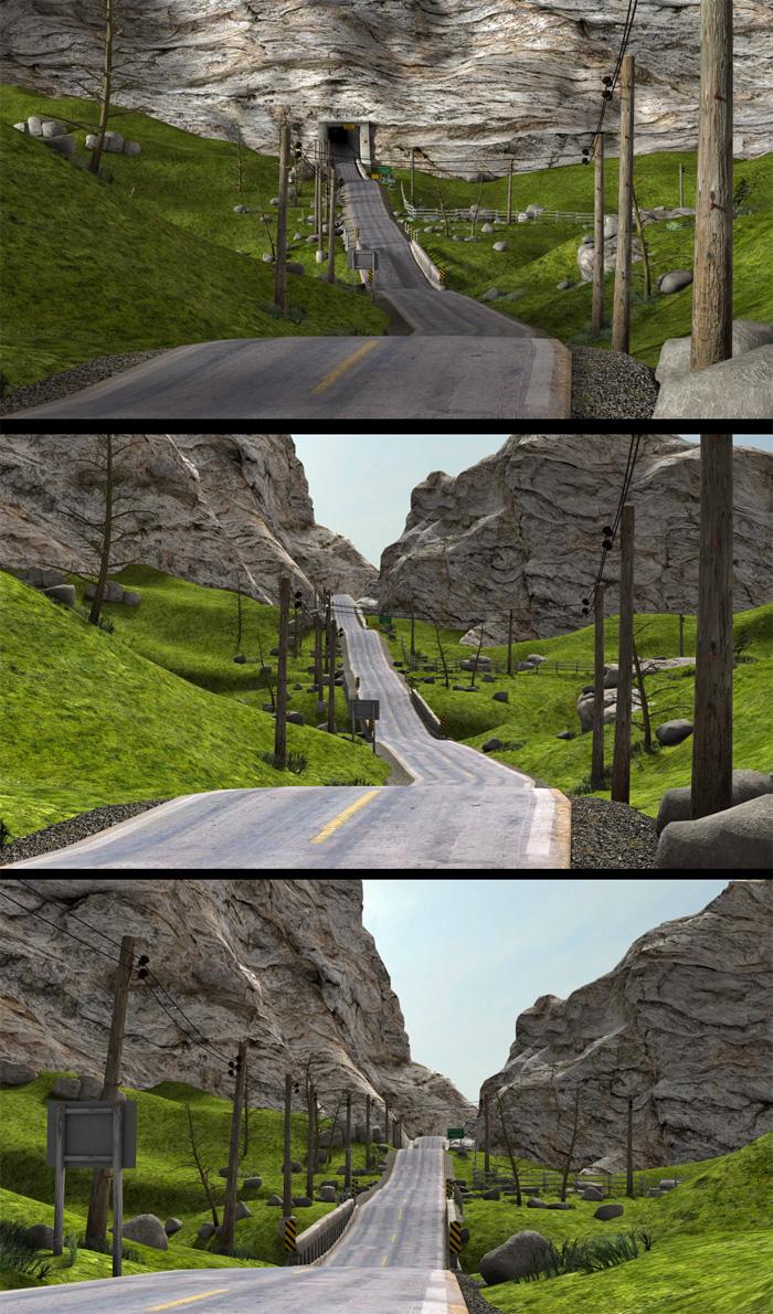
What's Next [coming soon] [Commercial]I had a question in PM regarding the Rural Crossroads set, whether or not the tunnel can be removed, and if the side roads can be hidden. The sideroads have their own material zones so they can be hidden in the surfaces tab by setting Opacity = 0. The tunnel is connected to the central mountain slope, so if it gets hidden or removed, there is a big void there, but luckily there are a couple additional mountain slopes on either side, that are individual props, which can be repositioned and rotated in the y-axis giving the illusion that the main road continues into the distance.
please note: used the Secluded Shoreline 3DL lightset for these renders.
 Gia 7 Thread
I loved Gia 6.
Again, the face has (almost) no personality, contrario to previous generation (6) where each babe was clearly identifiable.
But...
Positive side: the skin and the morph are wonderful. really. At last a really white person (likle caucasian in central europa or slavonic/slavic ).
In the bundle, there are at least 2 superbs items: UMA is AWESOME. And at last, we have a good ponytail. (do you know that it is the favorite hair of men for women? ). The geneva hair seems really nice. The node of the ponytail is a bit big. But we waited 7 month to have a decent ponytail (not as good as my 2 fav ones)
The Doctor Appreciation threadYes I agree that all of the greeblies would kill the poly count, and yes, it was those central consoles and the basic room layout itself that screamed "potential TARDIS design". A toned down version of the set with few to no greeblies would work for a custom TARDIS interior for people to decorate as they please, though, given that the set does feature passageways branching off (like they showed in the older Classic Who episodes, leading to the other TARDIS rooms).
As for your confusion about the room being the Death Star "office", I initially had the same feeling back then, and wondered why it wasn't in the film. Given that I had the pre-recorded VHS tape sold in stores back then (IIRC it was one of the very first cassettes we had for our "new" VCR back then) and watched it many times over the years, I eventually realized my mistake, which is a shame, the set would've fit in perfectly in the movie, if not on the Death Star, then at the Yavin IV base. Thanks to Facebook and TubeOffline, I now have that "Making of" special on my 2TB portable HD.
Target Helpers?I think the problem is that I don't understand the animation you want,. i've tried to ask if you can describe the motion of each part, or the whole thing, since that would help us to understand what you need to do to get that type of animation. ....but I think we'll get there, it's just a frustrating process at times.
The basic construction is correct,. but in the example of the tentacled beastie,. the model would be a simgle object,. rather than separate limbs unconnected to the body
it would have a central HIP, and all of the tentacles would come from that,.
that's what i meant by selecting the mesh and then you can detach the bones from it,
You mentiond that the Blue and Red sections were constructed with multiple cylinders,.
Try making these as single objects, rather than grouped structures.,.. Unless they are supposed to flex and move,... in which case each of thoise would require more bones.
bear in mind that the bones (once attached) have an influence over the vertices of the mesh object. and parts of your current mesh may be outside of that influence
this envelope of influence is normally adjusted in the vertex modeller,. using the Weight painting tools (another reason you should use a single object)
think of the bones as a magnet which influences the object
I think you're getting the Hip/foot thinnk just fine,. I think the construction of the object should be a single object
Have a look at this ,. https://dl.dropboxusercontent.com/u/7907045/Bones.car
now, i'm unsure whether you want the vertical stubs (Bone3 and Bone5) to be freely spinning around the main part,. If so,. then thse parts should be made as single objects without any bones, and simply parented in place on the main item.
If you want to connect Multiple versions of this object together,. then Bone2 and Bone6 can be either parented to, or use track, to follow the bones on another version of this.
Hope it helps
The Doctor Appreciation threadAs it has been 39 years since I saw that special, I somehow convinced myself their setting was that small Death Star "office" where R2 discovered the location of the Princess. Obviously, I was woefully confused.
Given the interior designs we've seen since the '96 movie, my following assessment doesn't carry as much weight, but personally, I find that set far too "greebled" . I guess what caught your eye was that central control station and the fact the floor bordering its plinth is a hexagon. I guess the overall "white" scheme resembles the "classic" console room. One thing you can't deny, modeling all those components and would send the polygon count through the roof!
Still, I want to thank you for posting that link. I have not seen that special since it debuted in Septemember 1977, over 39 years ago! Being 14 at the time and living with a grandmother on a fixed retirement, I couldn't afford the early videotaping technology that existed at that time. But I did use a cassette device to make an audio recording that I played many time over the next few years. Eventually, I either lost the tape or I wore out the media; I can't remember which. This is certainly a pleasant stroll down memory lane!
Sincerely,
Bill
Enjoying vertex modelling in DAZ CarraraI have a current project in which I will be using a simple shape and a curved polyline so I will show an example from that. I made a mistake but I think the steps might still be helpful. (My mistake was using an edge instead of an interior, which I will be fixing later). It is not a screw, but maybe the concept will still be recognizable.
I am modeling a pair of moccasins. Here is an example of using a simple shape and a sweep path to get a start on some laces. I will be using the central flaps of the moccasins to help define the sweep polyline path.
1) Modeled a pair of low poly moccasins (then copied all the polygons of one shoe mesh)
2) Inserted an new vertex object to be the laces for a moccasin. Pasted the shoe mesh that was copied in step 1.
3) Used construct : oval, and then reduced the scale to a tiny size, which is the circumference of a shoe lace.
4) Chose the curve tool from the polyline menu. Chose the preset that I wanted (pipeline) Then started at the top of one flap and crisscrossed points back and forth down the shoe flaps, and then back up.
5) Selected the oval. Chose Construct : Sweep. Carrara prompts for the polyline sweep path. Clicked the crisscrossed curve that I just made.
6) Carrara swept the oval along the path, but off to the side. No big deal, I selected the new mesh and translated it to the correct place.
7) I deleted the duplicate moccasin mesh, the oval and the polyline.
So, this will work as a concept, but I forgot to make the holes for the laces to go through, so I will have to do it over.
Daz 3D is part of

Connect
DAZ Productions, Inc.
7533 S Center View Ct #4664
West Jordan, UT 84084Licensing Agreement | Terms of Service | Privacy Policy | EULA
© 2026 Daz Productions Inc. All Rights Reserved.