Help unwrapping a "simple box top"
 Inkubo
Posts: 744
Inkubo
Posts: 744
Remember the old-style shoe boxes that had a separate box and lid? Imagine how you might take just the lid, which has a large horizontal top face and four thin vertical side faces, and flatten it to make one flat piece of cardboard. You'd flip it upside down on the table, tear the four corners, and fold the side faces down to lay flat with the top face.
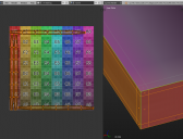
In Blender I have modeled a mat (a piece of carpet) that is conceptually identical to that shoebox lid with top and sides but no bottom. The only differences are that the vertical sides of the mat are very tiny, and there are extra edges in my model's faces for mesh regularity and reinforcement. To UV map the object, Blender has several modes to choose from, but I can't figure out how to get any* of them to simply unfold the model without distorting faces. (*There is an undesirable "lightmap pack" mode which keeps all the faces proportional, but scatters them around like a jigsaw puzzle, making the model extremely difficult to texture with a 2D paint program.) Whether I select the sides to UV map separately or just mark four seams on the corners where you would tear the shoebox lid, the perfectly rectangular sides unwrap into long octogons that are huge in proportion to the rest of the model. (See image.)
- Is there any way to tell Blender to avoid distorting faces whenever possible, and keep everything proportional?
- If not, is there any other UV mapping software you could recommend that does a better job simply unfolding models such as this, where you want to keep things regular, connected, and proportional?
I have attached a view of one of the box corners in an extreme closeup. You can see that I have added edges to reinforce sharpness in DAZ Studio, since it doesn't respect the "sharp" edge setting Blender can apply. The distance to the reinforcement lines might give you a clue as to how far in we're zoomed, and how very thin the vertical sides are supposed to be in relation to the rest of the model.
Daz 3D is part of 
Connect
DAZ Productions, Inc.
224 S 200 W, Suite #250
Salt Lake City, UT 84101
Licensing Agreement | Terms of Service | Privacy Policy | EULA
© 2024 Daz Productions Inc. All Rights Reserved.
Comments
I'm not familiar with Blender, but can't you use a cubic projection and then stitch the sides onto the top if necessary?
As for sharp edges, if you are not converting to SubD you just need to adjust the smoothign angle setting for the surfaces - if you are using SubD, use the Geometry Editor to select the edges (right-click>Selection Type>Edge Selection) and the assign an edge weight (right-click>Geometry Editing).
Richard,
I assume that with Edge Weight, a higher value means "keep it sharper"? Is this method preferred over adding reinforcement edges? I did the reinforcement thing because that's what you learn in tutorials like Fugazi's tutorial for using Hexagon. But modeling would be sooooo much easier without all those extra tiny faces! I'd say that on the objects I model for Sub-D, I end up with many more faces in the reinforced edges than I do in the entire rest of the model.
There are addons for blender one is called UV_Square
at 1:30 you see the button click that makes all UV-Square (the addon is in the UV-ImageEditor Tool-Shelf press [T] while mouse is over the UV-Editor to see).
But the wiki pages says its compatible with 2.71 - I dont know if its compatible with your latest blender version 2.79.
Another thing you can do is: go to Ortho(graphic) view eg. Left Ortho shortcut Ctrl+Numpad1 and then use the UV-Unwrap option "Project from View".
For the scaling try "average island scale" and "pack islands" found in the UV-Editor menu. Or if you cant find a command in the UI or dont remember the shortcut press Space and search in the text field for the command name.
Lateron you can manipulate the UV-Layout in the UV/Image-Editor just like you can edit the geometry in the 3D view. [B] = Box Selection [G] = grab [S] = Scale [R] = Rotate [X&Y] = press after G&S to limit manipultion to one of the 2D axis.
Yes, higher value is sharper. The main drawback of edge weighting (as far as I know) is that it is more application-specific, and not all formats support it (OBJ certainly doesn't, I think FBX and Collada do though my ability to export FBX from modo with weights seemed to vanish a while back).
I would delete the evenly spaced faces on the rim of the lid. Instead use edgeloops to form the edge just where needed. The shorter the distance between the edgeloops on the corner the sharper the edge will look with subdivisions applied.
I would try the following:
1. whit the base resolution geometry in blender , add a 'subdivision surface' modifier - to have it look something like with SubD in DS later
2. select the edgeloop on the upper corner then press Space and enter "bevel" to use the Bevel mesh tool, if you now move the mouse you can change the width of the bevel, then click to confirm - after that you also have options for the bevel segments in the ToolShelf to change influence, segments (maybe 2), and radius
Thanks for the suggestions, guys!
I'm torn about edge weighting now... I'd love to model without any reinforcing edges to keep my number of polygons down and make models that work better with beveling when I need it. But if the result only works right in DAZ Studio, customers who want to export for use in iClone or elsewhere will be frustrated. It's a dilemma.
Syrus, do you think having evenly spaced quads is generally a waste on hard-surface models? That I should just make faces as large as I can on objects that won't bend? Meaning, if I don't want my box top/carpet to be dForce compatible, I should just model it in exactly five faces and use edge weights instead of reinforcing edges to make it keep its shape when converted to SubD?
Maybe I'm not the one to talk about topology in general, but I know this general rule to only use as few faces as possible that are needed to hold the shape.
In the sceenshots I took you can see the Bevel Mesh Toll in action. Edit Mode + Edge Selection Mode + A + Move Mouse + click - then adjust in ToolShelf options.
The beveled edges are working aginst the subdiv modifier. This default cube should look rougthly the same if you import it without the subdiv modifier into DS and you convert it to SubD there.
Or you could apply the subdiv and imoprt a highres version into DS without using SubD.
I wasn't aware of that DazStudio uses its own edge weight system. How would someone archive the right beveled edges on hard surfaces: with highres base geometry, with DS build in edge weight, or a combination?
For a simple box top like that, I added my cuts and then selected the four corner edges and marked seams. I wanted to splay the box, so I didn't seam the top edges of the box. Selected all verts, pressed U and unwrapped.
The sides were angled, so I immediately pressed F6 and changed from angled to conformal and you see the result.
http://prntscr.com/iegmsb
I then turned the uvs 45 degrees to straighten them.
The common technics showen here should be adaptable to any other geometry editor. Sorry if Im posting too much blender screenshots.
1. the base geometry we start with
2. we had no face groups created before the bevel dont worry select the big middle face and press Ctrl and + the same time to expand selection - now you can asign the face groups - keep you organized with groups
3. press the Unwrap shortcut with polygon selection to only unwrap this
4. the Unwrap result spreads out into the 1 to 1 UV space border
5. press S to resize and G to drag this first single UV-Island away, out of your working space
6. Add another Vertex "Group" - border select in the bottom left UV-View the remaining UV points - asign vertex group - ofcourse you can also just select the "Top" group and invert with Ctrl+I
7. Unwrap the new "Group" and see what happens - this time blender is confused because no UV-Seams are defined - interesting result we are getting closer
8. select the only the outer edge loops and mark seams all around
9. Unwrap again, and again...
10. my first good default cube UV-Unwrap - a bit messy but at least I know which side is the "Top"
I did exactly what Cris is describing, with a couple of differences in my geometry: my box top was vastly larger than the four vertical sides, and everything was subdivided by edges spaced at regular intervals because that seemed to be the way it's done in the tutorials I've watched. The fact that you guys, Cris and Syrus, got such beautiful results from unwrapping is probably due to the fact that you didn't have any extra edges at all. I'm going to go back to my model and dissolve as many faces as possible, then try UV mapping again. I'll post my results.
Cris: would that model of a box you produced be considered a well-crafted model for use in DAZ Studio? You've added reinforcing edges, but otherwise kept the number of faces down to the minimum possible to define the shape. That's what I'd like to do, if it's good. I simply got the impression from the tutorials I've seen that geometry should have a regular mesh rather than being simple as possible. But maybe that's only true for organic and clothing shapes destined for rigging and weight maps? I'd like to know for sure what I should be shooting for.
Since you are considered about to use some kind of autogenerated SubDivision like the SubD in DS, you can have a look at the blender wireframe with 2 Subdivisions.
Also dont forget to turn on Smooth Shading in the ToolShelf - this you just have to do once for a new object. Now in Object mode the Solid display mode shows the cube with smooth edges.
Now we are dealing with 964 Vertecies for this simple cube, but the most of this is autogenerated and therefore easier to handle in a 3D scene.
Its just a matter of how close the object will be showen in front of the camera to decide how detailed it should be.
For texturing, it's going to depend on a few things.
If you're going to create 1:1 textures, specific to your model, and you do the textures where you can paint or project your textures, a low poly box is fine. If you plan to use seamless textures, you need to test to see if there is any stretching or compression due to how the model is cut.
I prefer to add geometry where it's needed as opposed to using subdivision because subdivision quadruples the entire object's geometry per level. Doing a good low poly model that the customer can use subdivision within DS, without the amount of geometry becoming bloated and hard to work with or render, is a good goal
You'd need to show what the whole model is; if it's just a simple box, it's unlikely it's going to be unique enough for a product. The more intricate your model, the more geometry it requires. Maybe show us what the final model will be.
I found a very informative tutorial for:
UV Unfolding, Unstretching & More in Blender
I would skip the beginning and fast forward to minute 6:30, where the different technics of using the blender UV editor getting explained like pining [P], stitching [V] and the sometimes confusing behaviour of this editor with its different settings - in this tutorial even the weirdest settings I never used before starts to makes sense.
And here is one explaning the Smooth Shading and the smoothing angle:
Subdivision Surfaces: Artifacts (explained simple)
Subdivision Surfaces: Overview (how shading and subdivision works together)
Another good tutorial I like to share, with my aproval.
My 5-sided box unwrapped almost perfectly after I dissolved all the extra edges I had included to get regularly spaced square faces. Now there are 12 edges to make the shape plus 16 edges for reinforcement, that's all, and seams on the four vertical corner edges for unwrapping. It unwrapped with the top tilted at a 45-degree angle, just as Cris found, and I had to rotate and scale it up to fill the UV area. For some reason, Blender doesn't try to maintain scale when unwrapping, so all the faces in the vertical sides that got splayed were way too large, but with so few edges, it was easy for me to move things around and put them back to scale.
Thanks, everyone! Syrus, I'm watching the video tutorial now.
I'm glad you mastered the Box unwraping. And while I was searching for good tutorials I also learned a bit of the basics like the overall shading angle and that specific edge weights are possible.
I hope you can use this knowledge to create more content for DAZ Studio, sometimes a render just needs some simple tiny props to be complete. Good if you know how to make them, when something like this is nowhere else to be found.
Instead of using the bevel mesh tool you can also use a overall bevel (all edges) modifier for that. I mean before the unwrap - to concentrate on the shape and the proportions - while box-modeling the so called 'cage mesh' - then you can take care of the reinforcement edges much later in the process.
If you realy want to get most out of blender and learn advanced technics you should use some of these non-destructiv modifiers in the parameters palet.
Its the same with the head unwrap - you can save yourself half of the work, especialy with the seams on the ears, if you first box select exactly half of the model and delete one side. Then add a Mirror modifier on the x axis, next you can get the geometry / topology right and unwrap this one side, with the UV-mirror option in the modifiers settings (U & V are basicly like x & y in the 2D space). Place the UV islands on the left or right side in the UV space, apply the mirror modifier and then stich the mirrored UV islands together later - even if you dont stich them you get perfectly mirrored UV-islands that you can texture easily in a 2D image editor.
I actualy once tryed another box modeling.
This is the result of my attempt a few moths ago to model a tissue dispenser box.
I think run into trouble with the overall geometry becuase I made it with tris everywhere instead of using quads. You can see I thought of having the front/back and left/right side of the box overlaping in the UV layout. If you start adding text and logos to your texture, you also have to take care of the right direction of the UV island here on the sides of the box. Changing that is easy just select the side where the texture is mirrored the wrong way, in the UV editor press S, X and enter -1, now the selected part is fliped on the X axis.
Then while exporting the OBJ file I turned off to save the "Write Normals" and imported it into DS but the default shading angle there didnt look that pretty even with SubD.